Sales hot line ( 24 hours service): 18037961302
E-Mail: firstfurnace@gmail.com
whatsapp:+8618037961302
Adress: Luoxin Industrial Park, Luoyang, HenanLarge diameter steel pipe quen
Piston rod quenching and tempe
Grinding rod quenching and tem
High frequency induction heate
Quenching equipment for machin
Round steel end heating furnac
Steel pipe heat treatment prod
Square steel quenching and tem
Sucker rod quenching and tempe
Thickened petroleum steel pipe
Round steel quenching and temp
Steel pipe quenching and tempe
Steel plate quenching and temp
Induction Hardening Machine&nb
Flywheel ring gear high freque
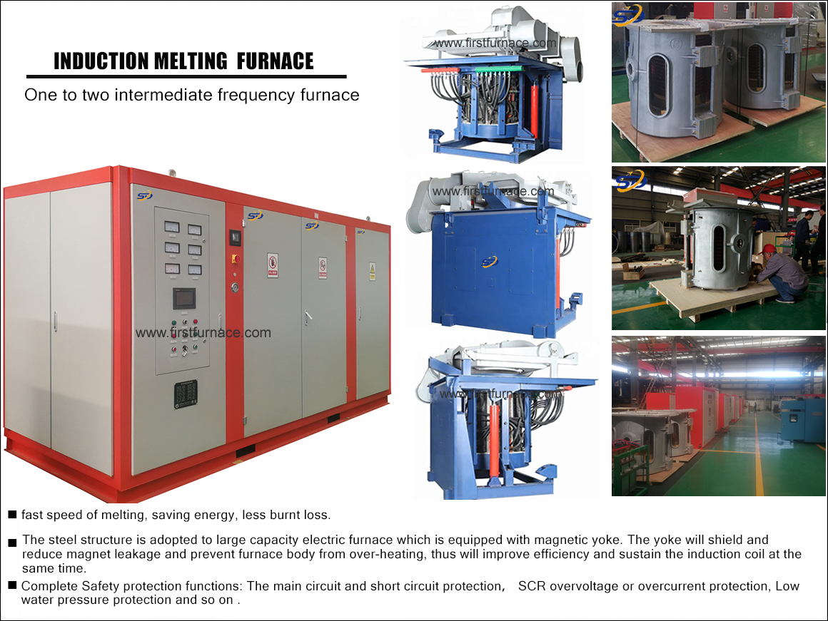
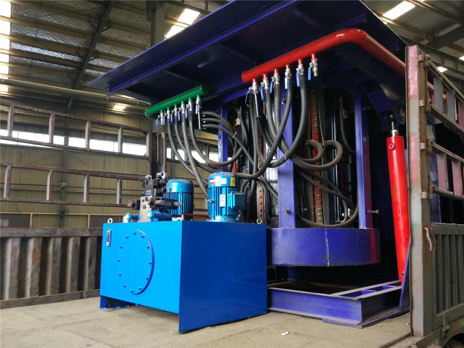
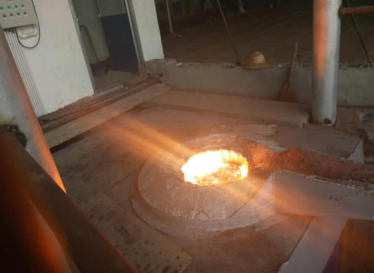
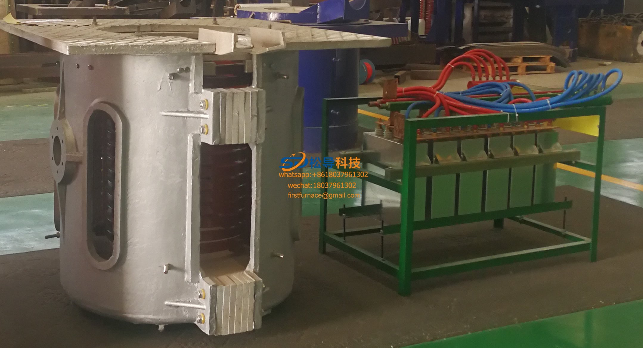
induction melting furnace working principle - parallel resonance frequency power supply
The power supply of the induction melting furnace adopts the parallel resonance intermediate frequency power supply, which is the earliest application of intermediate frequency power supply in China. It is a frequency conversion device that converts three-phase power frequency AC electrical energy into single-phase intermediate frequency electrical energy. Its advantage is that it has strong load adaptability and can be used as the power supply for induction melting furnace .
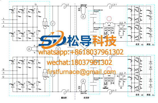
Figure 2-1 shows the principle diagram of the main circuit of the parallel resonant intermediate frequency power supply, which is mainly composed of isolating switch (DK), AC contactor (or electric circuit breaker KM), incoming line inductance (L1 ~ L3), and fast coupler ( FU), rectifier (VT1 ~ VT6), smoothing reactor (LF), inverter (VT7 ~ VT10), parallel resonant load (L, C) . The rectifier converts the three-phase power frequency alternating current into direct current; the smoothing reactor is used to filter the rectified current ripple and isolate different ripple voltages between the rectifier and the inverter; the inverter converts the direct current into a single-phase intermediate frequency Alternating current; the parallel resonant load composed of an inductor and a compensation capacitor can better adapt to the change of load properties during the heating process.

Figure 2-1 Parallel resonance intermediate frequency power supply main circuit
( 1) Three-phase bridge-type fully-controlled rectifier circuit The rectifier circuit of the parallel resonant intermediate frequency power supply adopts a three-phase bridge-type fully-controlled rectifier circuit. The principle is shown in Figure 2-2. Since the smoothing reactor (LF) has a large inductance and the load is an inductive load, the load current output by the rectifier is continuous and a straight line. When aW60° , the output waveform of the rectifier circuit is the same as that of the resistive load, and the conduction law is the same as that of the resistive load. When a>60° , due to the effect of the inductor LF , the thyristor will still be turned on after the power supply voltage crosses zero, until the next thyristor is triggered to turn on, so that a negative area appears in the waveform of the rectifier output voltage, but the rectifier output current is still One level

Wire. When the control angle increases to 90. When the positive and negative areas in the output voltage waveform are equal, the average value of the output voltage Ud=0. When a>90° , the rectifier circuit works in the active inverter working state. The phase shift range of the rectifier circuit of the intermediate frequency power supply is 0°~150°.
( 2) Inverter circuit Figure 2-3 is a schematic diagram of the parallel inverter circuit. The capacitor C in the load circuit is connected in parallel with the inductor coil L , and the commutation is based on the principle of parallel resonance, so it is called a parallel resonance inverter circuit. The DC voltage Ud provided by the thyristor fully-controlled rectifier circuit is continuously adjustable, and the parallel inverter circuit inverts the DC power into an intermediate frequency AC power supply to the load. The DC side string has a large filter inductance LF, so it is a current-type inverter. Because the operating frequency is relatively high, the thyristors of the 4 bridge arms of the inverter circuit adopt fast thyristors. L7 ~ L10 are the commutation inductance of the inverter thyristor, which is used to limit the current rise rate of the thyristor during commutation.

Figure 2-3 Schematic diagram of parallel inverter circuit
Iron induction furnace
Aluminum melting furnace
Copper melting furnace
Small steel melting furnace
Small induction melting furnace
Induction iron furnace
3T intermediate frequency iron melting f

0.25T Intermediate Frequency Furnace

0.5T Intermediate Frequency Furnace

Medium Frequency Furnace

2T Induction Melting Furnace

1T Induction Melting Furnace

500kg Induction Melting Furnace

250kg Induction Melting Furnace

Induction Melting Furnace

3 T Induction Melting Furnace

5T Induction Melting Furnace
1T One Belt Two Intermediate Frequency F

5T One Belt Two Intermediate Frequency F
3T One Belt Two Intermediate Frequency F
2T One Belt Two Intermediate Frequency F
5T Parallel Intermediate Frequency Furna

5T Intermediate Frequency Furnace

5T Series Intermediate Frequency Furnace
3T Series Intermediate Frequency Furnace
2T Series Intermediate Frequency Furnace
1T Series Intermediate Frequency Furnace
0.5T Series Intermediate Frequency Furna

0.25T Series Intermediate Frequency Furn
1T Parallel Intermediate Frequency Furna
2T Parallel Intermediate Frequency Furna
0.5T Parallel Intermediate Frequency Fur