Sales hot line ( 24 hours service): 18037961302
E-Mail: firstfurnace@gmail.com
whatsapp:+8618037961302
Adress: Luoxin Industrial Park, Luoyang, HenanLarge diameter steel pipe quen
Piston rod quenching and tempe
Grinding rod quenching and tem
High frequency induction heate
Quenching equipment for machin
Round steel end heating furnac
Steel pipe heat treatment prod
Square steel quenching and tem
Sucker rod quenching and tempe
Thickened petroleum steel pipe
Round steel quenching and temp
Steel pipe quenching and tempe
Steel plate quenching and temp
Induction Hardening Machine&nb
Flywheel ring gear high freque
High-frequency induction heating equipment debugging technology
Debugging of high frequency induction heating equipment
It must be debugged normally before use. Follow the steps below to check the inverter:
1 power supply for the control part (note: do not connect the large air switch of the main circuit), press the door on the cabinet door
Inverter start button (green button), adjust the power adjustment knob clockwise to the maximum position, use a two-wire oscilloscope to observe whether the drive signal on the control pole of each IGBT module is normal ( a square wave with a pulse of about 50% , pulse width)
The top is about +15V and the rest is about -8V . Rising and falling edges . 1 [mu] S or less, the two bridge arm
The dead zone of the IGBT gate pulse is greater than 2 Μ s ), and confirm that the IGBT drive signals of the same bridge arm are in phase (the error of the upper and lower edges cannot exceed 0.5 Μ s ), and the IGBT drive signals of the upper and lower arms Must be in reverse.
2 check of the rectification pulse. Press the start button, the gates of the three SCRs should have a column of pulses with amplitude greater than 1.8V, pulse width 50%, and pulse frequency of approximately 10kHz .
3 pressure test. Large air switch with main circuit (do not control voltage switch). At this point, the pointer of the DC voltmeter should be raised to 500V or more. Observe whether the equipment is normal (no abnormal sound, no odor, no breakdown of each device), keep it for 10 minutes, and turn off the main power switch. At this time, DC
The pressure automatically drops to zero.
4 High-frequency induction heating equipment Follow the steps below to start the inverter.
Pass the cooling water and check if the cooling water passages are normal. Turn the power adjustment knob counterclockwise to the minimum position, and then combine the water pump switch, the control power switch, and the main power switch. Note that the DC voltage meter can rise to nearly 500V with the charge . Press the start button, delay 2 seconds to start in the right inverter. The relevant tables should have corresponding instructions. Gradually increase the power adjustment knob clockwise, and the DC current and power meter indications will immediately increase and reach the given value. At this point the device has entered normal operation. The equipment manufacturer sends personnel to adjust the protection settings to the required values (the equipment has been basically adjusted before leaving the factory, and can be adjusted as needed on site).
5 main control board potentiometer description
P1 - Adjust the intermediate frequency current waveform head to make it close to the sine wave and leave about 200 angles.
P2 - Adjust the mid-frequency current cutoff value.
P3 - Adjust the frequency of the current frequency current.
P8 - Adjust the value of the intermediate frequency current protection value.
P9 - Adjust the frequency of current protection.
P10 - Frequency meter calibration.
6 Stop as described below.
First turn the power adjustment knob counterclockwise to the minimum position, press the inverter stop button, and the medium frequency sound stops immediately. Turn off the main power switch, then observe the DC voltmeter drops to zero, then finally turn off the control power switch, water pump
switch.
7 high frequency induction heating equipment main control board signal indicator description:
|
name |
effect |
name |
effect |
|
L3 |
Input power indication |
L4 |
Input power indication |
|
L5 |
+15V power indicator |
L6 |
-15V power indicator |
|
L7 |
+5V power indicator |
L8 |
Grid protection indication |
|
L9 |
Water temperature water pressure power supply indication |
L10 |
Inverter pulse work instruction |
|
L11 |
Inverter pulse work instruction |
L12 |
Rectified pulse working instruction |
|
L13 |
Module protection indication |
L1 |
IF overcurrent protection indication |
|
L2 |
Power frequency overcurrent protection indication |
|
|
8 External protection board signal indicator description:
|
name |
effect |
name |
effect |
|
ILED1 |
Input power indication |
ILED2 |
External circulation water pressure protection indication |
|
ILED3 |
External circulation water pressure protection indication |
ILED4 |
Grid undervoltage protection indication |
|
ILED5 |
Grid overvoltage protection indication |
ILED6 |
Internal circulation water pressure protection indication |
|
ILED7 |
Internal circulation water pressure protection indication |
ILED8 |
Internal circulation water temperature protection indication |
|
ILED9 |
Cabinet internal environmental temperature protection indication |
|
|
9 Warning: After the main power switch is turned on and the inverter is started, it is forbidden to test any part with an oscilloscope or with a meter. Otherwise, the fault will be caused by the access of the parameters outside the test end of the instrument.
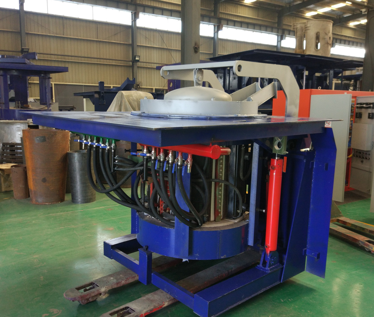
Iron induction furnace
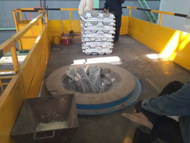
Aluminum melting furnace
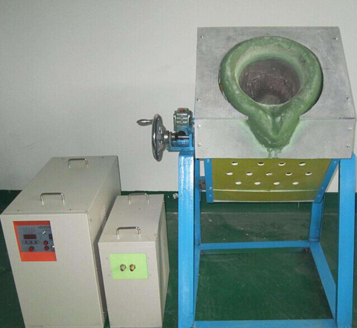
Copper melting furnace
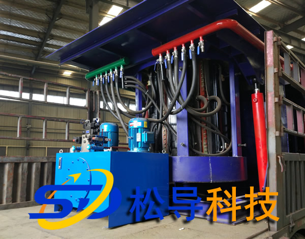
Small steel melting furnace
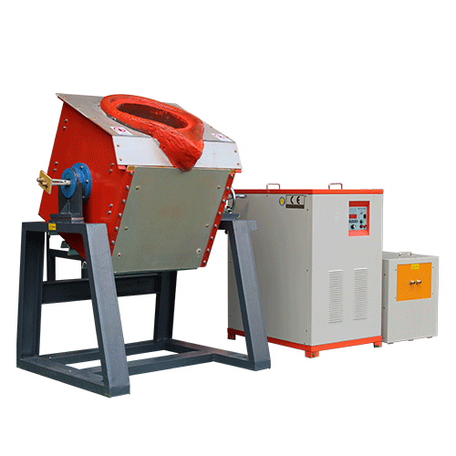
Small induction melting furnace
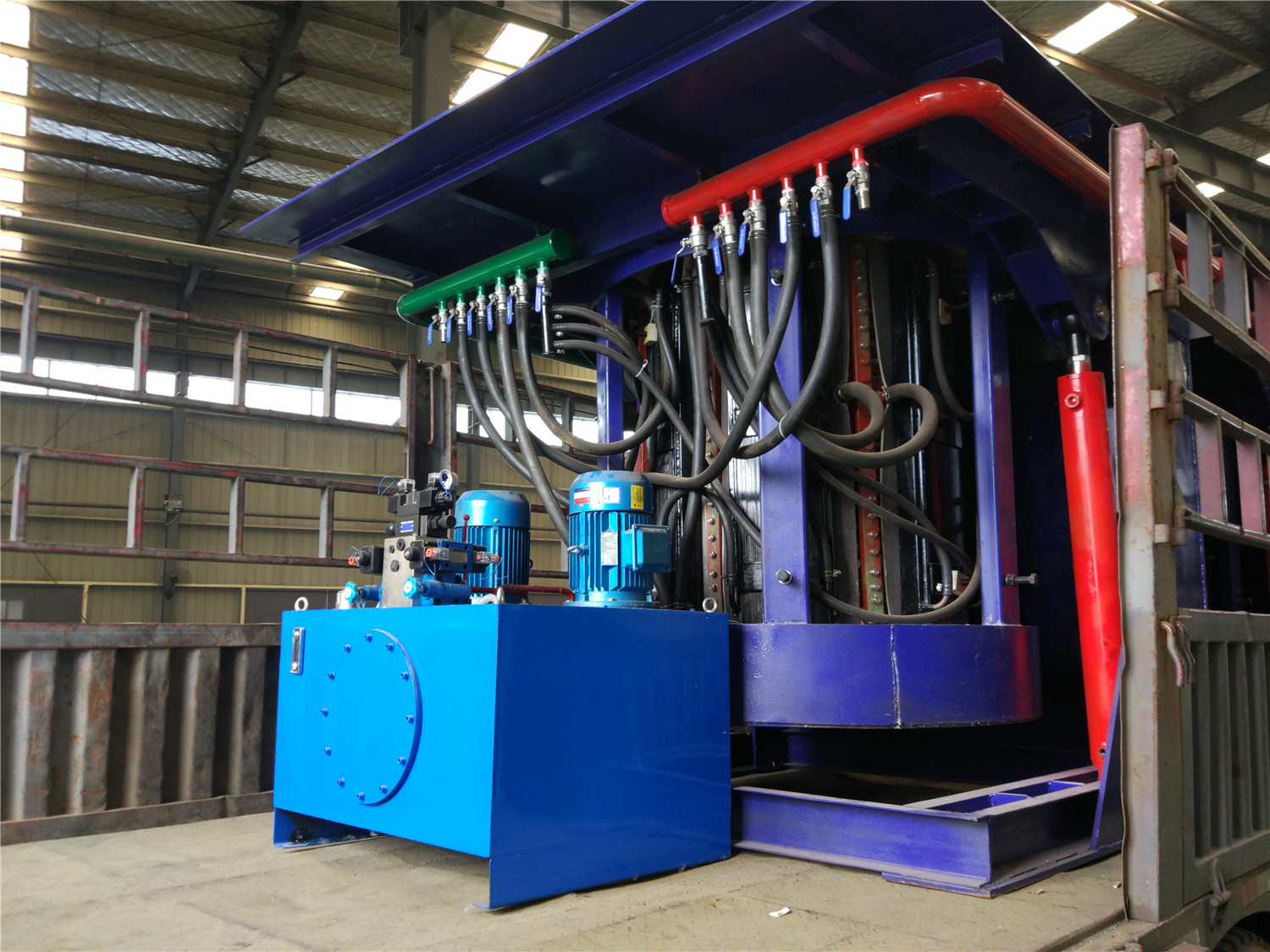
Induction iron furnace
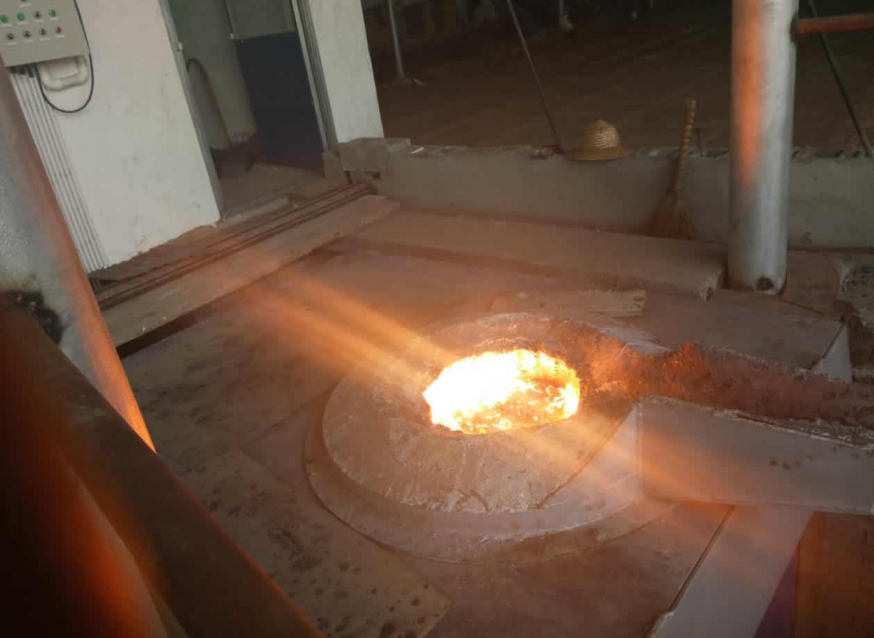
3T intermediate frequency iron melting f
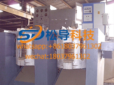
0.25T Intermediate Frequency Furnace
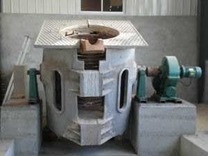
0.5T Intermediate Frequency Furnace
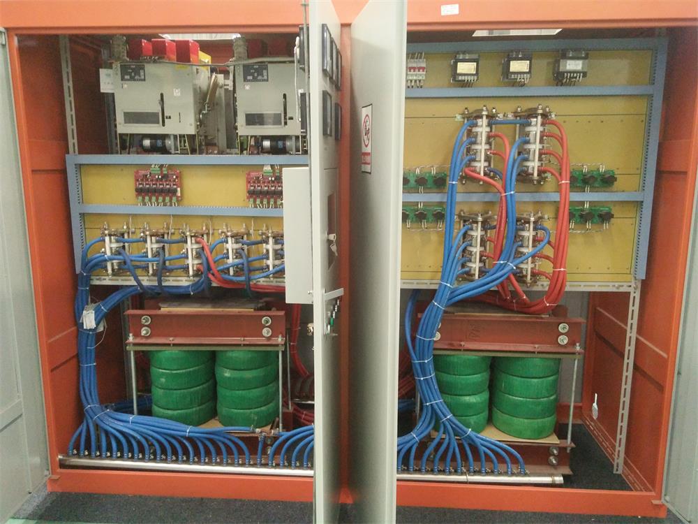
Medium Frequency Furnace

2T Induction Melting Furnace
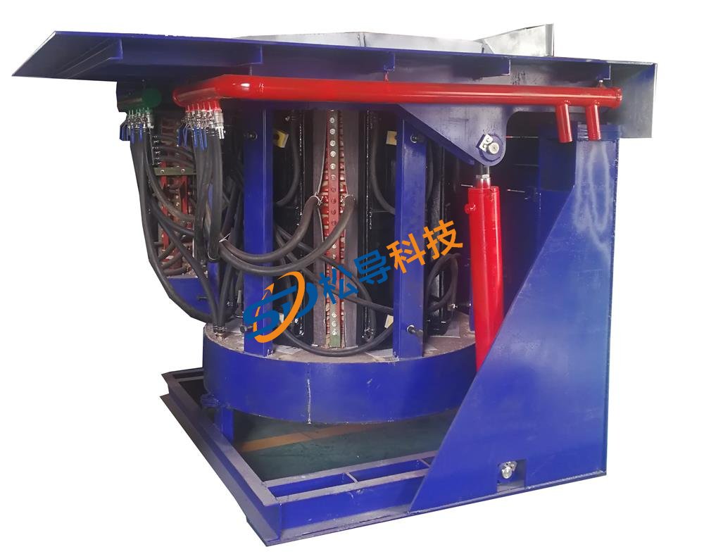
1T Induction Melting Furnace
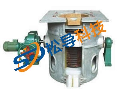
500kg Induction Melting Furnace
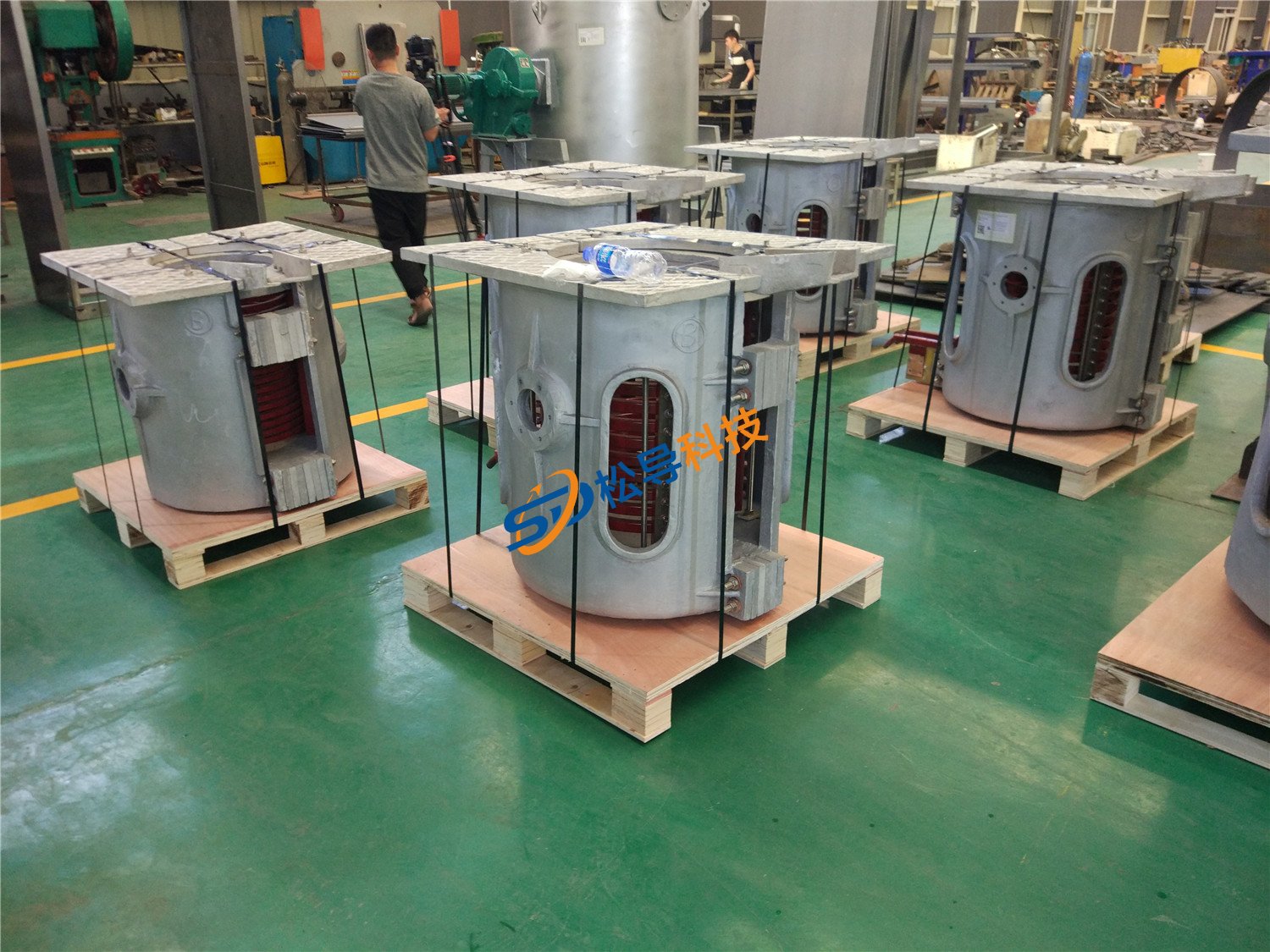
250kg Induction Melting Furnace
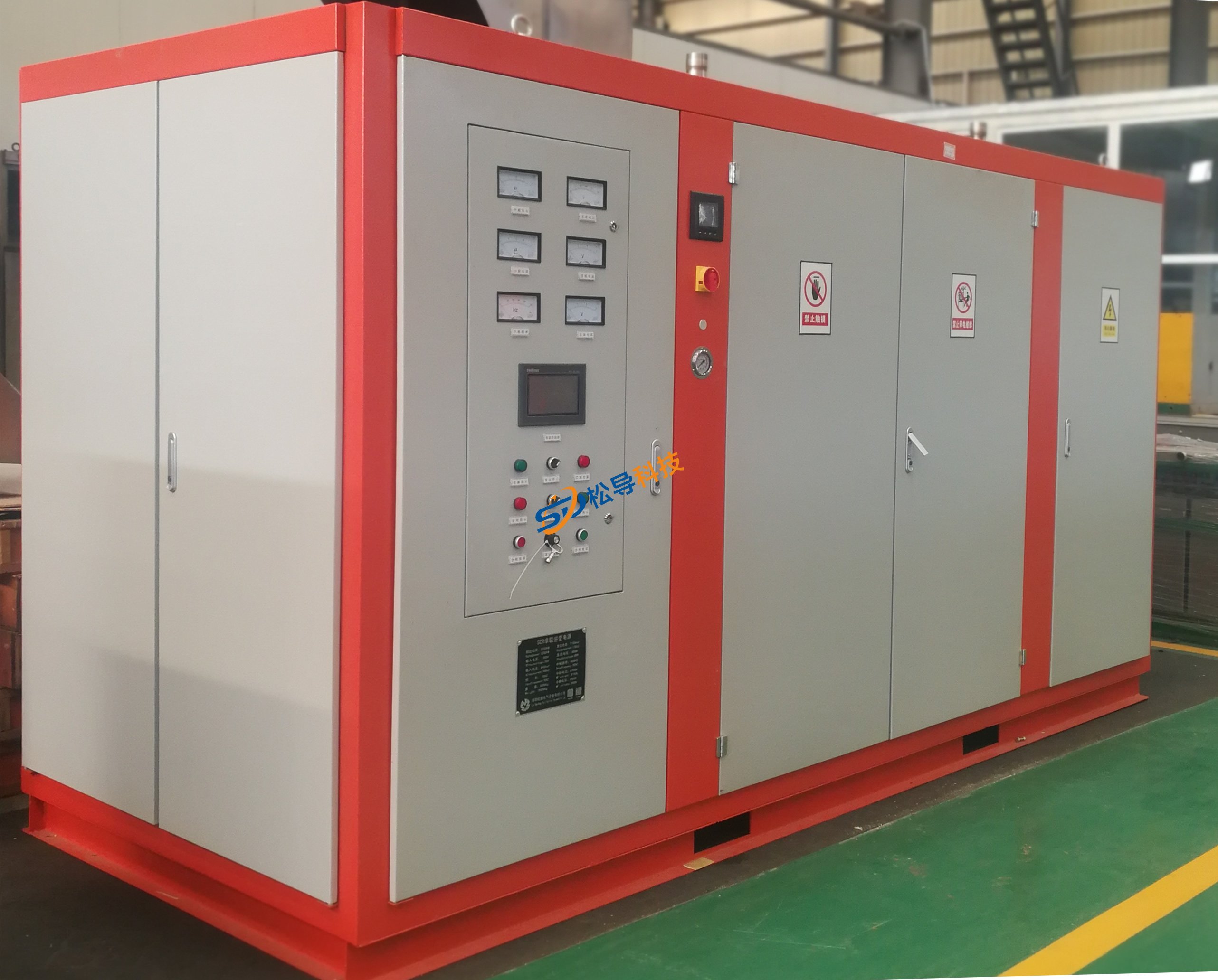
Induction Melting Furnace
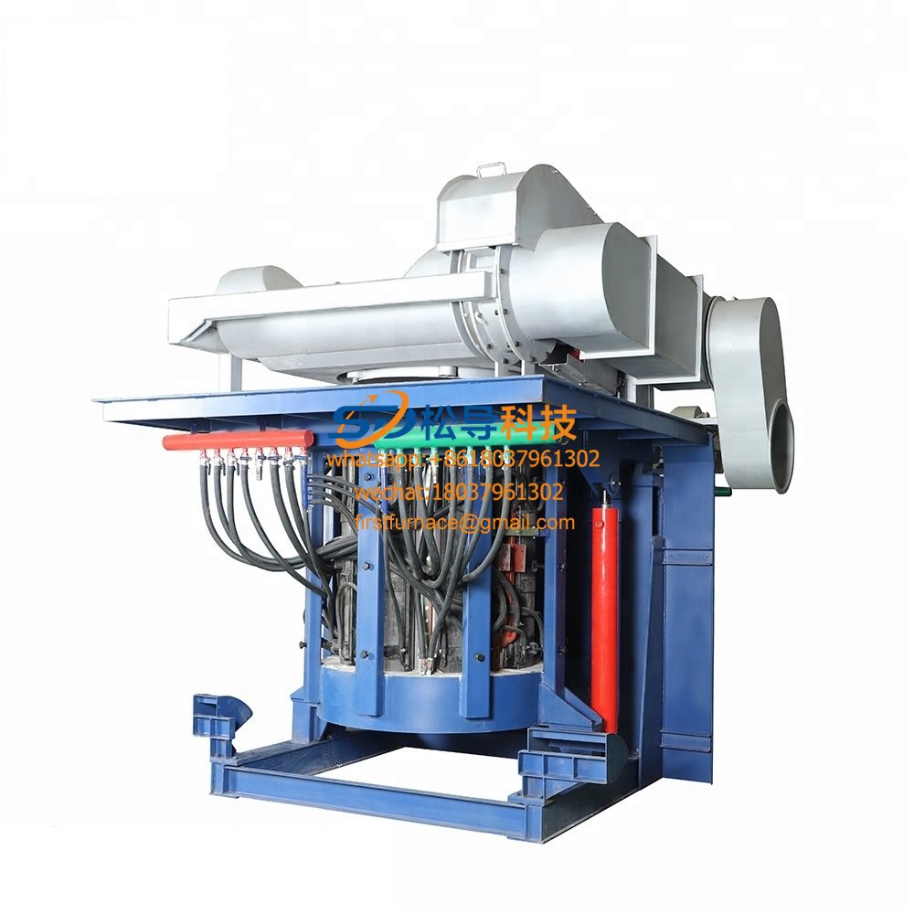
3 T Induction Melting Furnace
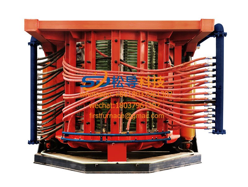
5T Induction Melting Furnace
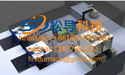
1T One Belt Two Intermediate Frequency F

5T One Belt Two Intermediate Frequency F
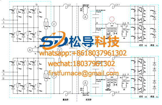
3T One Belt Two Intermediate Frequency F
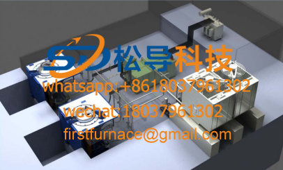
2T One Belt Two Intermediate Frequency F
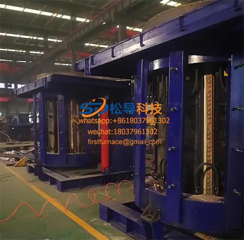
5T Parallel Intermediate Frequency Furna
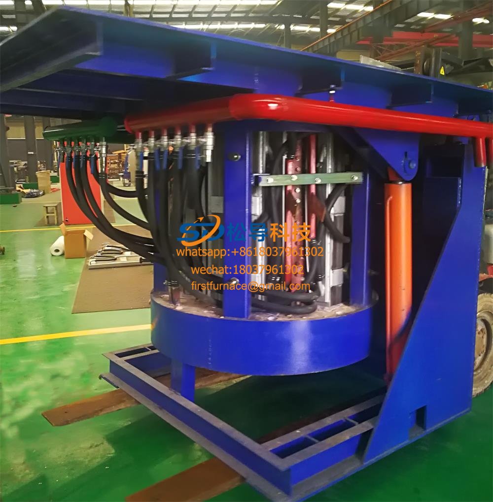
5T Intermediate Frequency Furnace

5T Series Intermediate Frequency Furnace
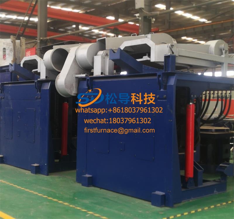
3T Series Intermediate Frequency Furnace
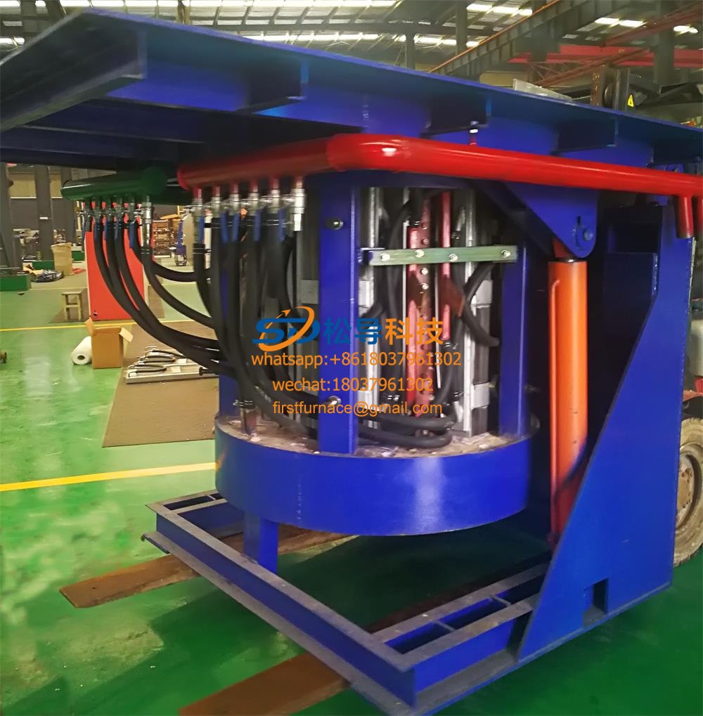
2T Series Intermediate Frequency Furnace
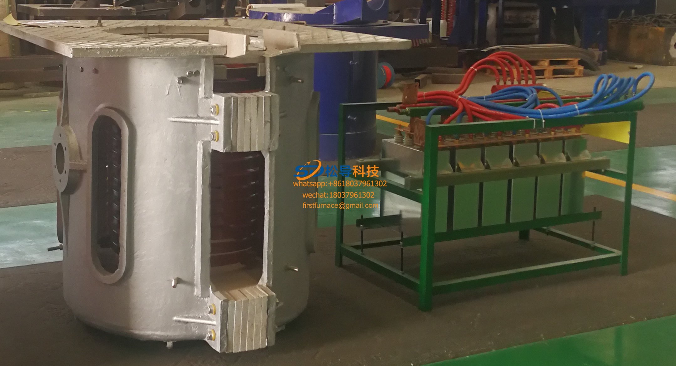
1T Series Intermediate Frequency Furnace
0.5T Series Intermediate Frequency Furna

0.25T Series Intermediate Frequency Furn
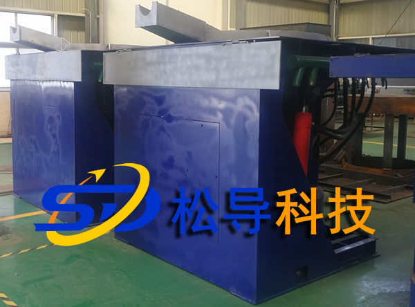
1T Parallel Intermediate Frequency Furna
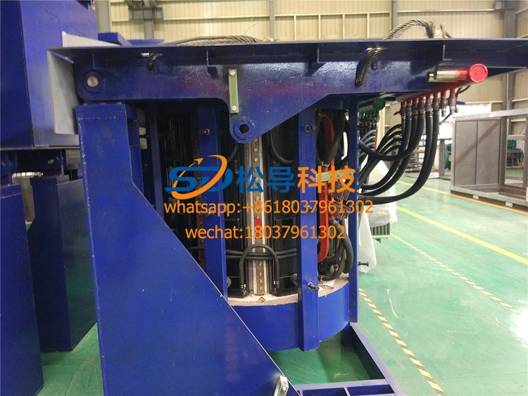
2T Parallel Intermediate Frequency Furna
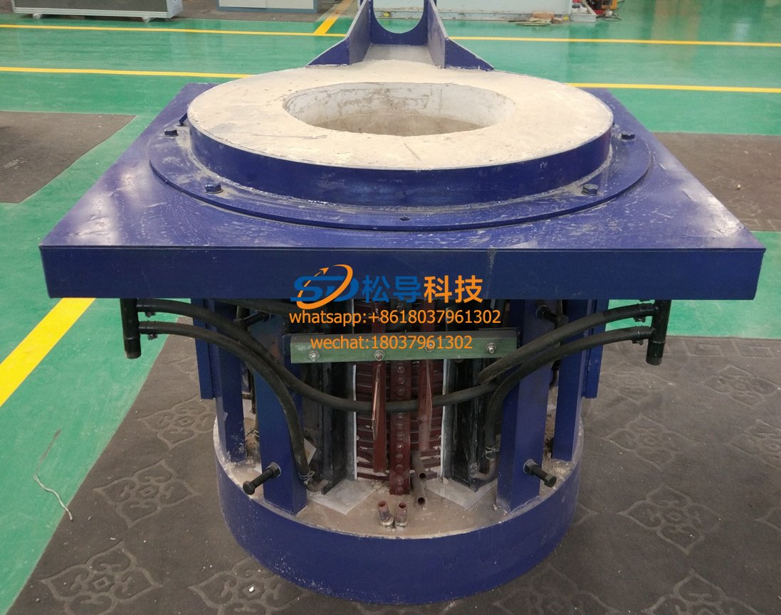
0.5T Parallel Intermediate Frequency Fur


