Sales hot line ( 24 hours service): 18037961302
E-Mail: firstfurnace@gmail.com
whatsapp:+8618037961302
Adress: Luoxin Industrial Park, Luoyang, HenanLarge diameter steel pipe quen
Piston rod quenching and tempe
Grinding rod quenching and tem
High frequency induction heate
Quenching equipment for machin
Round steel end heating furnac
Steel pipe heat treatment prod
Square steel quenching and tem
Sucker rod quenching and tempe
Thickened petroleum steel pipe
Round steel quenching and temp
Steel pipe quenching and tempe
Steel plate quenching and temp
Induction Hardening Machine&nb
Flywheel ring gear high freque
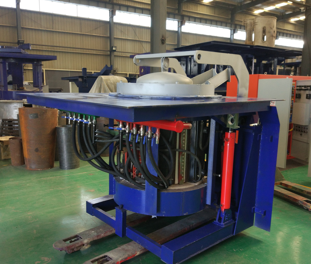
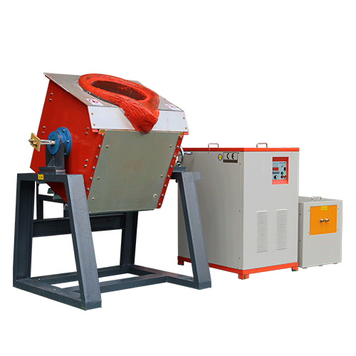
Important inspection method for repairing induction melting furnace
Induction melting furnace maintenance: The induction melting furnace main circuit (circuit breaker) is closed manually and automatically. For systems that are automatically closed, the power cord should be temporarily disconnected to ensure that the main circuit does not close. After the control power is turned on, the following aspects can be checked.
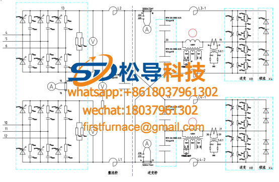
1. Connect the oscilloscope probe to the gate and cathode of the rectifier thyristor. The oscilloscope is placed in the power supply synchronization. After pressing the start button, the trigger pulse waveform can be seen. It should be double pulse and the amplitude should be greater than 2V. Press the stop button and the pulse will disappear immediately. Repeat six times, look at each thyristor. If there is no pulse at the gate, you can move the probe of the oscilloscope to the original side of the pulse transformer. If there is a pulse on the primary side and the secondary side does not, the pulse transformer is damaged, otherwise the problem It may be on the transmission line or on the main control board.
2. Connect the oscilloscope probe to the gate and cathode of the inverter thyristor. The oscilloscope is placed in the internal synchronization. After the control power is turned on, the inverter trigger pulse can be seen. It is a series of sharp pulses, and the amplitude should be greater than 2V. The pulse period is read out and the trigger pulse frequency is calculated. When normal, it should be about 20% higher than the nominal frequency of the power cabinet. This frequency is called the starting frequency. When the start button is pressed, the pulse spacing increases and the frequency becomes lower. Normally, it should be about 40% lower than the nominal frequency of the power cabinet. Press the stop button and the pulse frequency immediately jumps back to the starting frequency. Through the above checks, it is basically possible to eliminate faults that cannot be started at all. After starting, the work is not normal, generally in the following aspects:
1. Induction melting furnace maintenance rectifier phase loss: the fault is that the sound is not normal when working, the maximum output voltage rises below the rated value, and the power cabinet blame becomes louder. At this time, the output voltage can be lowered at about 200V, and the rectifier is observed with an oscilloscope. The output voltage waveform (the oscilloscope should be placed in the power supply synchronization), the normal input voltage waveform has six waveforms per cycle, and there will be two missing phases, as shown in Figure 2. This fault is generally caused by a thyristor of the rectifier that does not have a trigger pulse or a non-conduction of the trigger. In this case, first look at the gate pulse of the six rectifier thyristors with an oscilloscope, and if so, use a multimeter 200Ω file after shutdown. With each gate resistance, you can replace the thyristor that is not connected or has a particularly large gate resistance.
2. The induction melting furnace repairs the inverter three-bridge arm work: the fault is characterized by a particularly large output current, and the same is true for the empty furnace, and the sound of the power cabinet is very heavy. After starting, the power knob is adjusted to the minimum position, and the intermediate frequency output voltage is found. Higher than normal. The voltage waveform between the anode and cathode of the four inverter thyristors is sequentially observed by an oscilloscope, and each waveform of the normal one is as shown in FIG. If the three-bridge arm works, it can be seen that the waveforms of two adjacent thyristors in the inverter are normal, and the other two adjacent ones have no waveform, the other is only a sine wave, and the KK2 is not activated, and its anode-cathode The waveform between them is a sine wave; at the same time, KK2 will not turn on, which will cause KK1 to not turn off, so there is no waveform at the two ends of KK1.
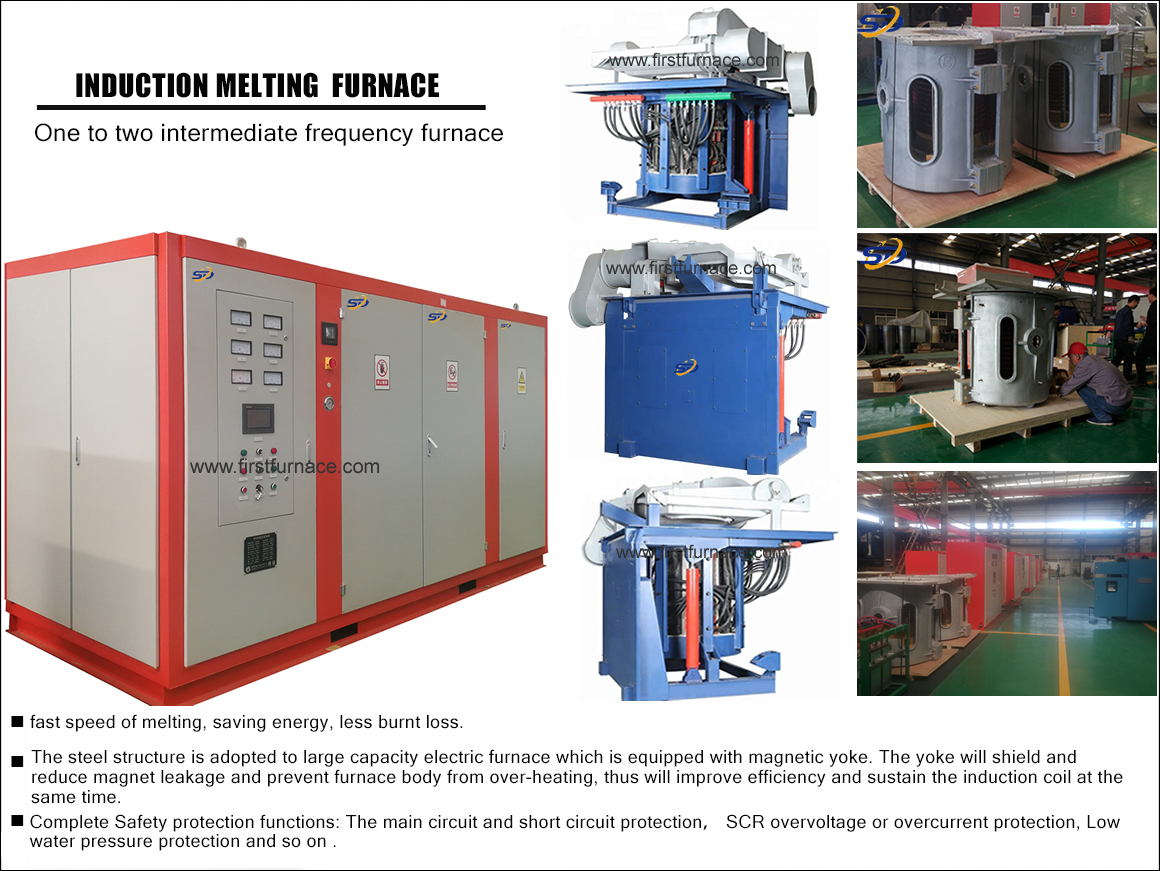
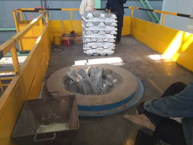
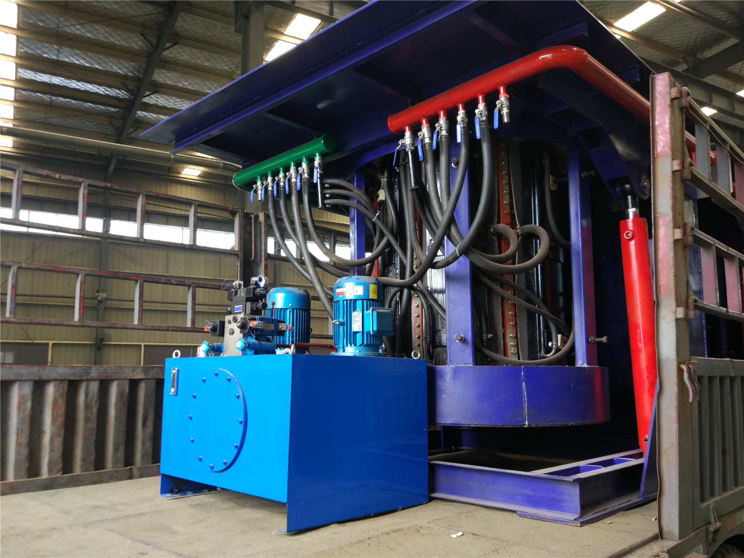
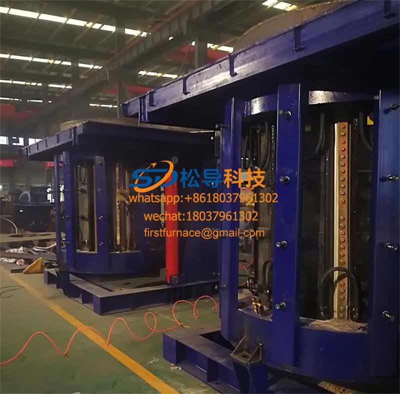
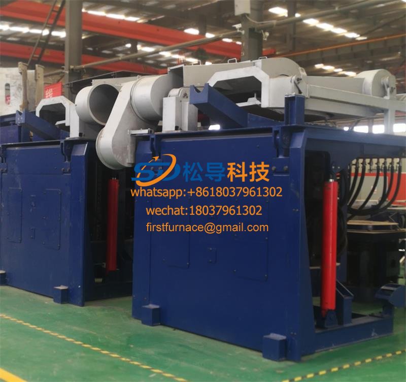
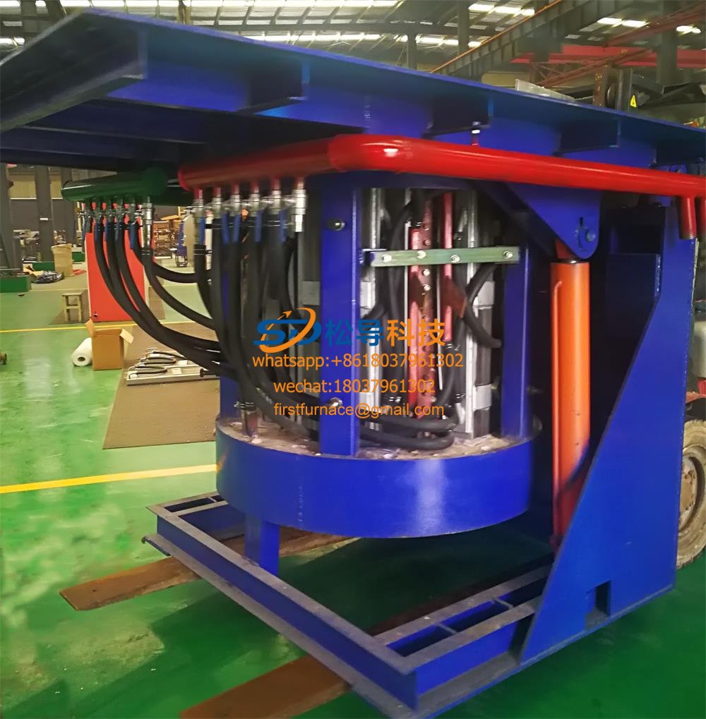
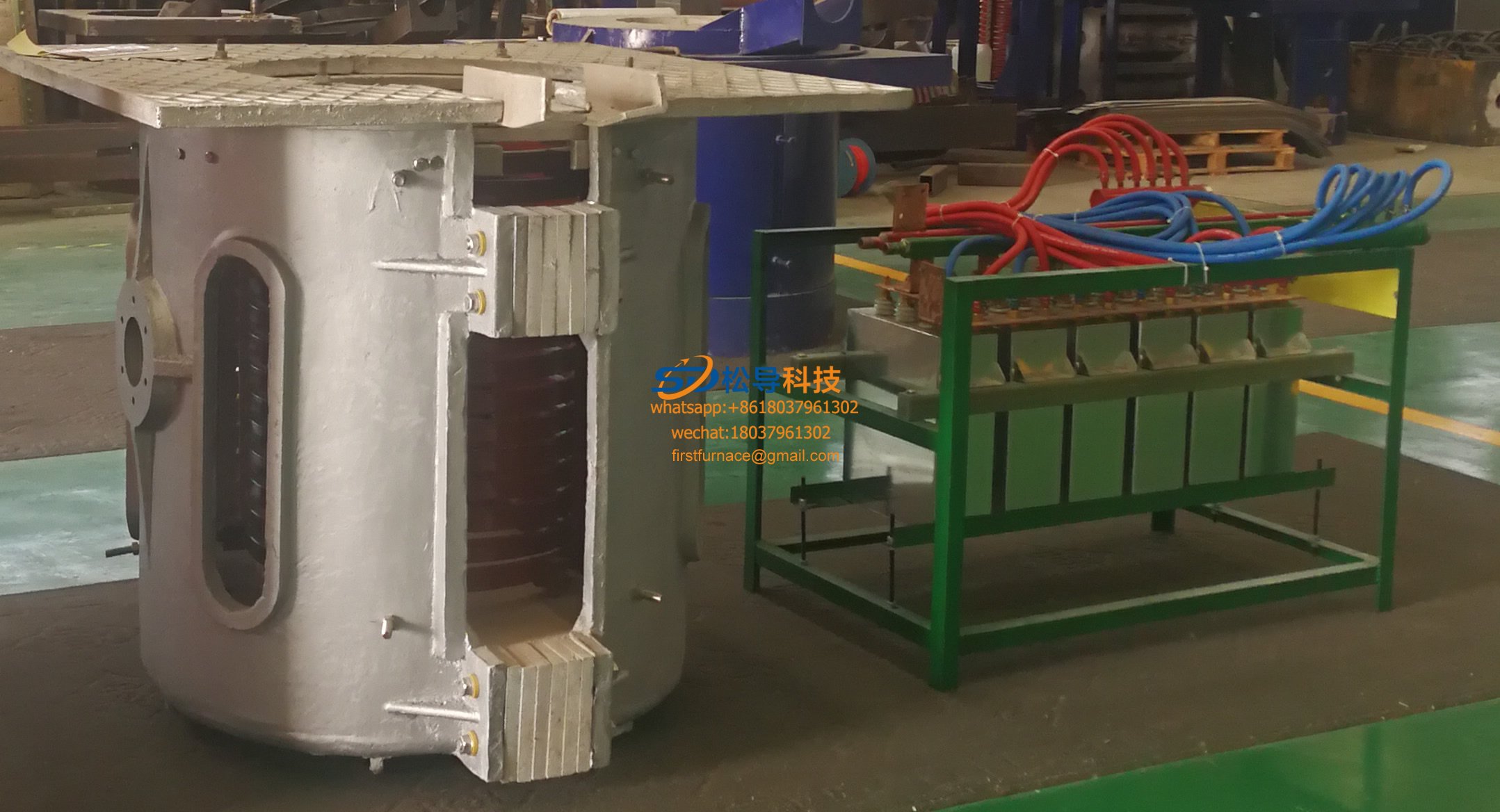
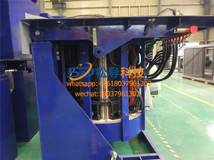
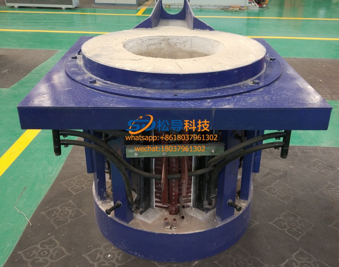
3. Induction melting furnace repair induction coil failure: The induction coil is the load of the intermediate frequency power supply, and it is made of a square copper tube with a wall thickness of 3 to 5 mm. Its common faults are as follows:
The induction coil leaks water, which may cause the coil to ignite between the turns, and must be repaired in time to run.
The load scraping induction coil will cause the copper tube to burn through, and the gap must be adjusted in time to remove the scale and impurities.
Induction coils are short-circuited between turns, and such faults are particularly prone to occur in small-sized medium-frequency induction furnaces. Because the furnace is small, it is deformed by thermal stress during operation, resulting in a short circuit between turns, and the fault is characterized by a large current and a higher operating frequency than usual. .
In summary, in order to use the correct method for fault repair of intermediate frequency power supply, it is necessary to be familiar with the characteristics and causes of common faults of intermediate frequency power supply, in order to reduce detours, save time, eliminate faults as soon as possible, and restore normal operation of intermediate frequency power supply. In order to ensure the smooth progress of production.
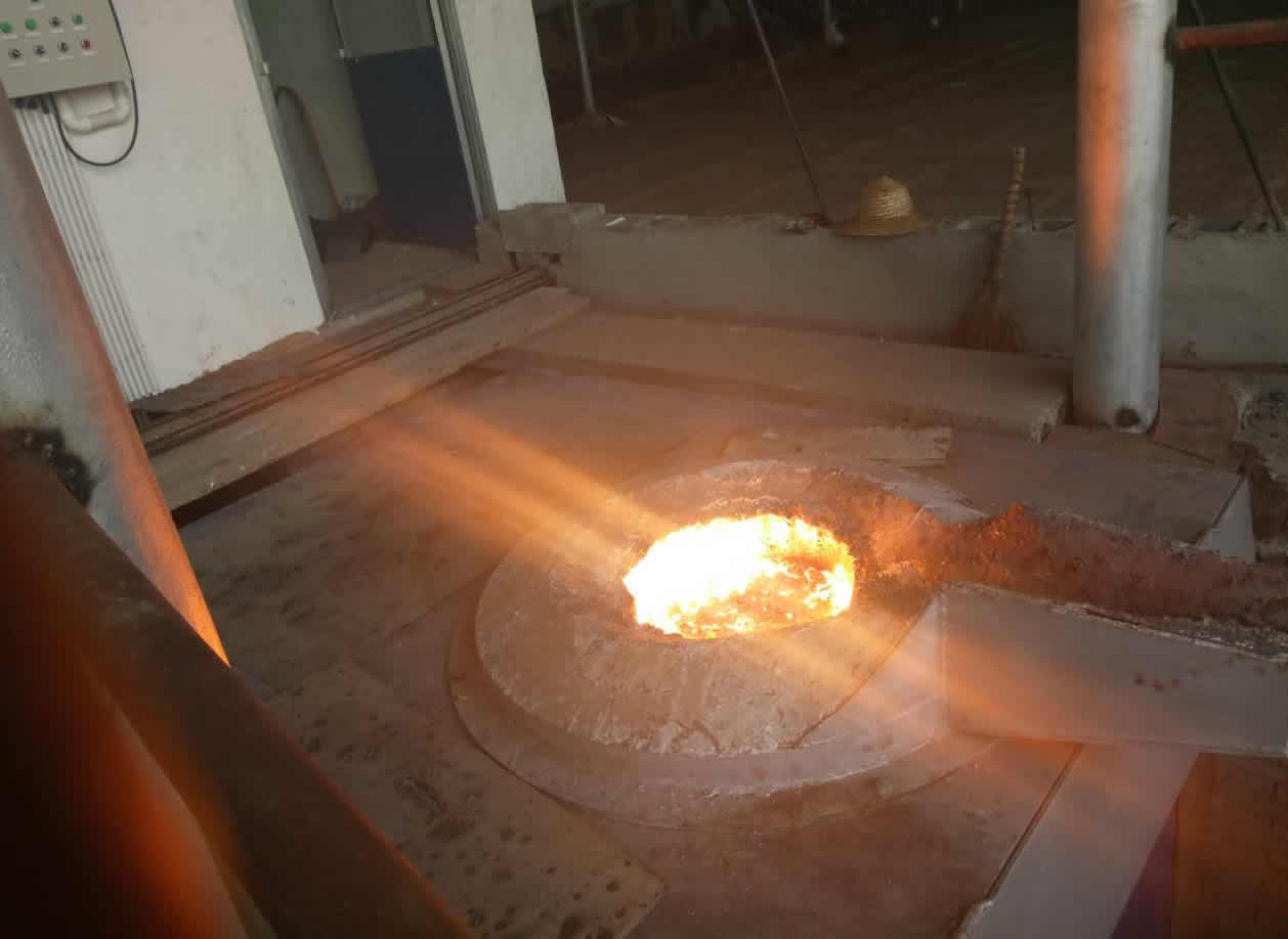
Iron induction furnace
Aluminum melting furnace
Copper melting furnace
Small steel melting furnace
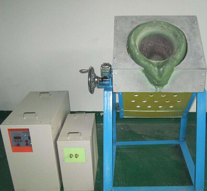
Small induction melting furnace
Induction iron furnace
3T intermediate frequency iron melting f

0.25T Intermediate Frequency Furnace

0.5T Intermediate Frequency Furnace

Medium Frequency Furnace

2T Induction Melting Furnace

1T Induction Melting Furnace

500kg Induction Melting Furnace

250kg Induction Melting Furnace

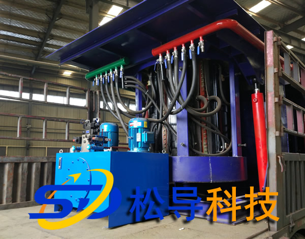
Induction Melting Furnace

3 T Induction Melting Furnace

5T Induction Melting Furnace
1T One Belt Two Intermediate Frequency F

5T One Belt Two Intermediate Frequency F
3T One Belt Two Intermediate Frequency F
2T One Belt Two Intermediate Frequency F
5T Parallel Intermediate Frequency Furna

5T Intermediate Frequency Furnace

5T Series Intermediate Frequency Furnace
3T Series Intermediate Frequency Furnace
2T Series Intermediate Frequency Furnace
1T Series Intermediate Frequency Furnace
0.5T Series Intermediate Frequency Furna

0.25T Series Intermediate Frequency Furn
1T Parallel Intermediate Frequency Furna
2T Parallel Intermediate Frequency Furna
0.5T Parallel Intermediate Frequency Fur