Sales hot line ( 24 hours service): 18037961302
E-Mail: firstfurnace@gmail.com
whatsapp:+8618037961302
Adress: Luoxin Industrial Park, Luoyang, HenanLarge diameter steel pipe quen
Piston rod quenching and tempe
Grinding rod quenching and tem
High frequency induction heate
Quenching equipment for machin
Round steel end heating furnac
Steel pipe heat treatment prod
Square steel quenching and tem
Sucker rod quenching and tempe
Thickened petroleum steel pipe
Round steel quenching and temp
Steel pipe quenching and tempe
Steel plate quenching and temp
Induction Hardening Machine&nb
Flywheel ring gear high freque
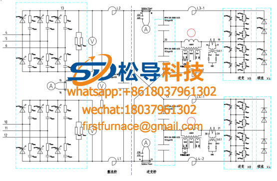
Analysis of common faults of zero voltage starting IF power supply control board
1. After the control switch is closed, the indicator on the control panel does not light. The possible causes of this failure are:
1) If the control switch is broken, use the test pencil or multimeter to measure whether the incoming and outgoing ends of the control switch are energized or voltage is normal. If it is not normal, confirm the cause of the fault and take corresponding measures to make the voltage normal.
2) The intermediate frequency power transformer is broken or the wiring is not secure. Firstly, the wiring is tightened. If it is still not perfect, you can disconnect one terminal of the transformer and use a multimeter to measure the on/off condition of the transformer. If the coil is broken, the power transformer needs to be replaced.
3) Control the power supply to break, use the test pencil to measure, and then replace the insurance after confirmation.
2. The main circuit air switch cannot be closed.
1) The water pressure is low and the water pressure relay is not connected. Try to make the water pressure normal.
2) The air switch loses voltage to protect the coil from power. Check the voltage loss protection circuit to eliminate the fault of the line and make the coil energized.
3) The air switch is closed and jumps. There may be a short circuit in the main circuit, which should be carefully checked to eliminate the short circuit fault and then send power. Or because the trip current of the air switch is not set correctly, it should be re-tuned.
3. The static DC voltage is abnormal.
1) The AC input voltage is low.
2) The phase of the rectified output is missing, check whether the output pulse of the control board is normal, whether the thyristor control electrode and the cathode wiring are reliable, and check whether the fast melting is normal.
3) The connection points of the main circuit are not in good contact.
4) The rectifier thyristor is broken.
4. The device cannot be started.
1) The inverter pulse is not normal.
2) The inverter check switch is not set to the self-excited gear ( working position ) .
3) The current transformer on the intermediate frequency capacitor is broken or the wiring is wrong. Replace the terminals of the transformer or measure the on and off of the transformer.
4) The voltage signal wiring on the intermediate frequency transformer is incorrect.
5) The potentiometer of the voltage or current signal is damaged or the wiring is not reliable. The wiring should be fixed or the potentiometer should be checked and repaired.
6) Is the incoming resistance (5W, 470--600Ω) on the control board damaged?
7) Check if the complete circuit of the voltage and current integrated signals is incorrect.
8) The IF capacitor is shorted or damaged.
9) The induction coil has a short circuit between turns or a short circuit to ground.
10) The inverter bridge circuit is faulty.
5. The static DC voltage is normal, and the voltage cannot rise after the load is applied.
1) The current limit adjustment value is too low. At this time, the equipment should have an abnormal sound of “ 嗡嗡 ” , and the current limit setting potentiometer can be adjusted to make it work normally.
2) The pressure limit adjustment value is too low, as in the above method adjustment.
3) There is a thyristor breakdown or no operation in the inverter bridge. Observe the trigger pulse and the waveform at both ends of the thyristor with an oscilloscope, so that the corresponding measures can be taken to eliminate the fault after confirmation.
4) Other parts of the inverter bridge are faulty.
6. The device works normally, the voltage suddenly drops, and there is an abnormal sound of “ 嗡嗡 ” .
1) There is a thyristor breakdown or no operation in the rectifier bridge.
2) There is a thyristor breakdown or no operation in the inverter bridge.
3) There is a fast-melting damage in the rectifier bridge.
4) The pressure limit or current limit is caused by the action.
7. After the overvoltage is adjusted, adjust the voltage limiting potentiometer and overvoltage protection action.
This is a normal phenomenon. The limit voltage setting potentiometer should be adjusted to the proper position, and the overvoltage setting value should be re-adjusted according to the debugging instructions to make it work stably.
8. When the voltage rises to the maximum during operation, the current is lower and the power is lower.
1) The capacitance of the parallel resonant capacitor is too small, and the capacitor should be added.
2) The current can be changed by changing the number of turns of the induction coil.
3) The thickness of the lining can be changed to change the current.
9 Static DC voltage cannot be fully turned on.
1) The phase sequence is wrong, and any two-phase line can be adjusted.
2) Adjust the power potentiometer resistance is wrong.
3) The protection circuit is always in motion.
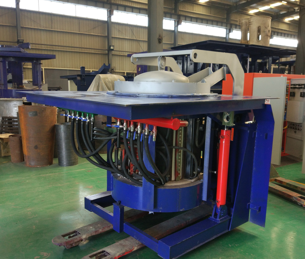
Iron induction furnace
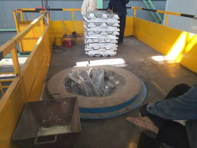
Aluminum melting furnace
Copper melting furnace
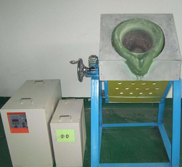
Small steel melting furnace
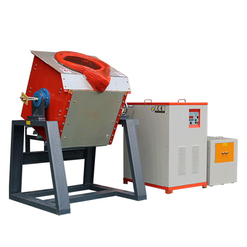
Small induction melting furnace
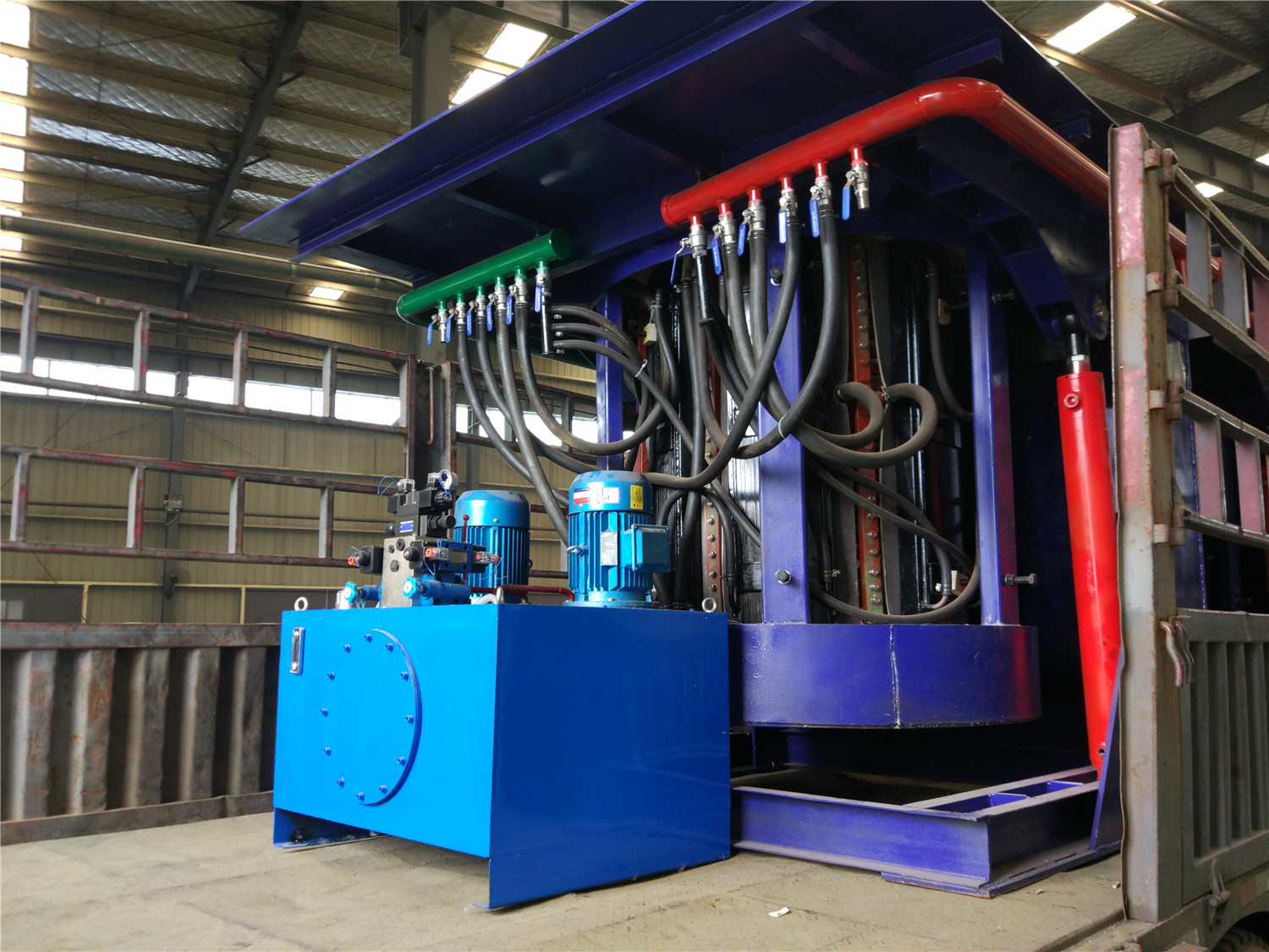
Induction iron furnace
3T intermediate frequency iron melting f

0.25T Intermediate Frequency Furnace

0.5T Intermediate Frequency Furnace

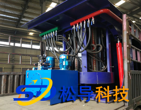
Medium Frequency Furnace

2T Induction Melting Furnace

1T Induction Melting Furnace

500kg Induction Melting Furnace

250kg Induction Melting Furnace

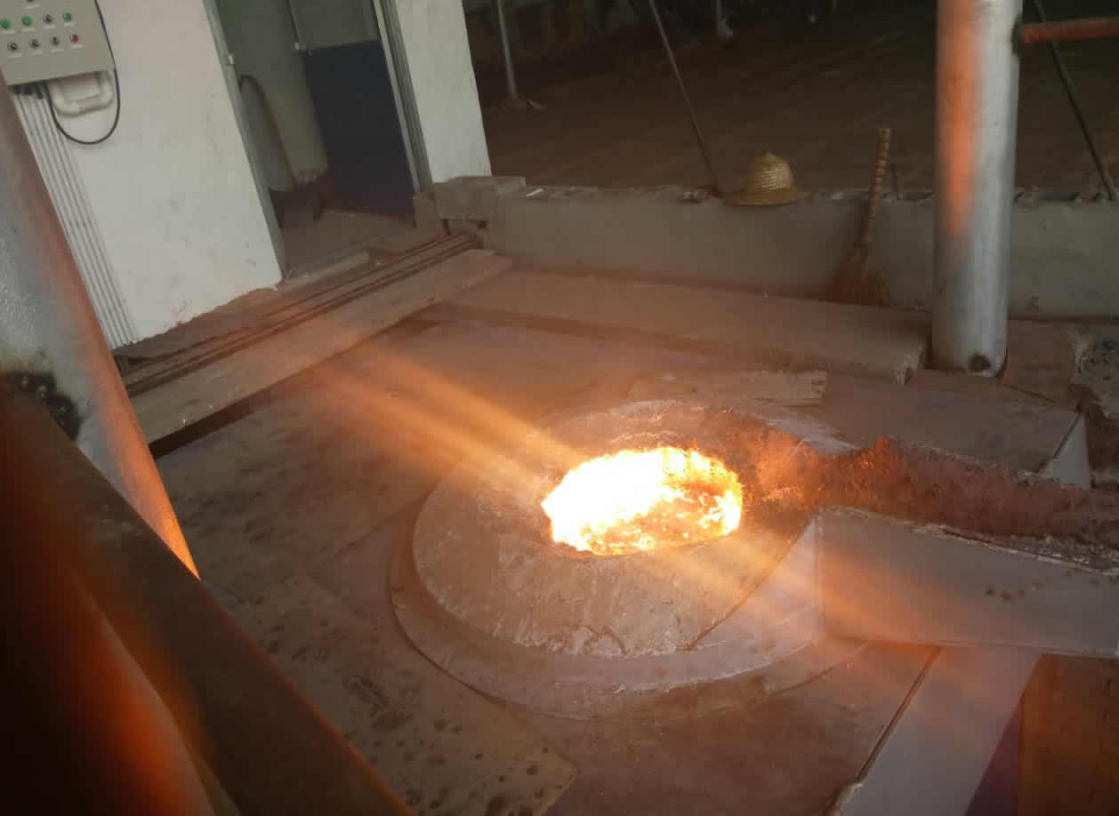
Induction Melting Furnace

3 T Induction Melting Furnace

5T Induction Melting Furnace
1T One Belt Two Intermediate Frequency F

5T One Belt Two Intermediate Frequency F
3T One Belt Two Intermediate Frequency F
2T One Belt Two Intermediate Frequency F
5T Parallel Intermediate Frequency Furna

5T Intermediate Frequency Furnace

5T Series Intermediate Frequency Furnace
3T Series Intermediate Frequency Furnace
2T Series Intermediate Frequency Furnace
1T Series Intermediate Frequency Furnace
0.5T Series Intermediate Frequency Furna

0.25T Series Intermediate Frequency Furn
1T Parallel Intermediate Frequency Furna
2T Parallel Intermediate Frequency Furna
0.5T Parallel Intermediate Frequency Fur