Sales hot line ( 24 hours service): 18037961302
E-Mail: firstfurnace@gmail.com
whatsapp:+8618037961302
Adress: Luoxin Industrial Park, Luoyang, HenanLarge diameter steel pipe quen
Piston rod quenching and tempe
Grinding rod quenching and tem
High frequency induction heate
Quenching equipment for machin
Round steel end heating furnac
Steel pipe heat treatment prod
Square steel quenching and tem
Sucker rod quenching and tempe
Thickened petroleum steel pipe
Round steel quenching and temp
Steel pipe quenching and tempe
Steel plate quenching and temp
Induction Hardening Machine&nb
Flywheel ring gear high freque

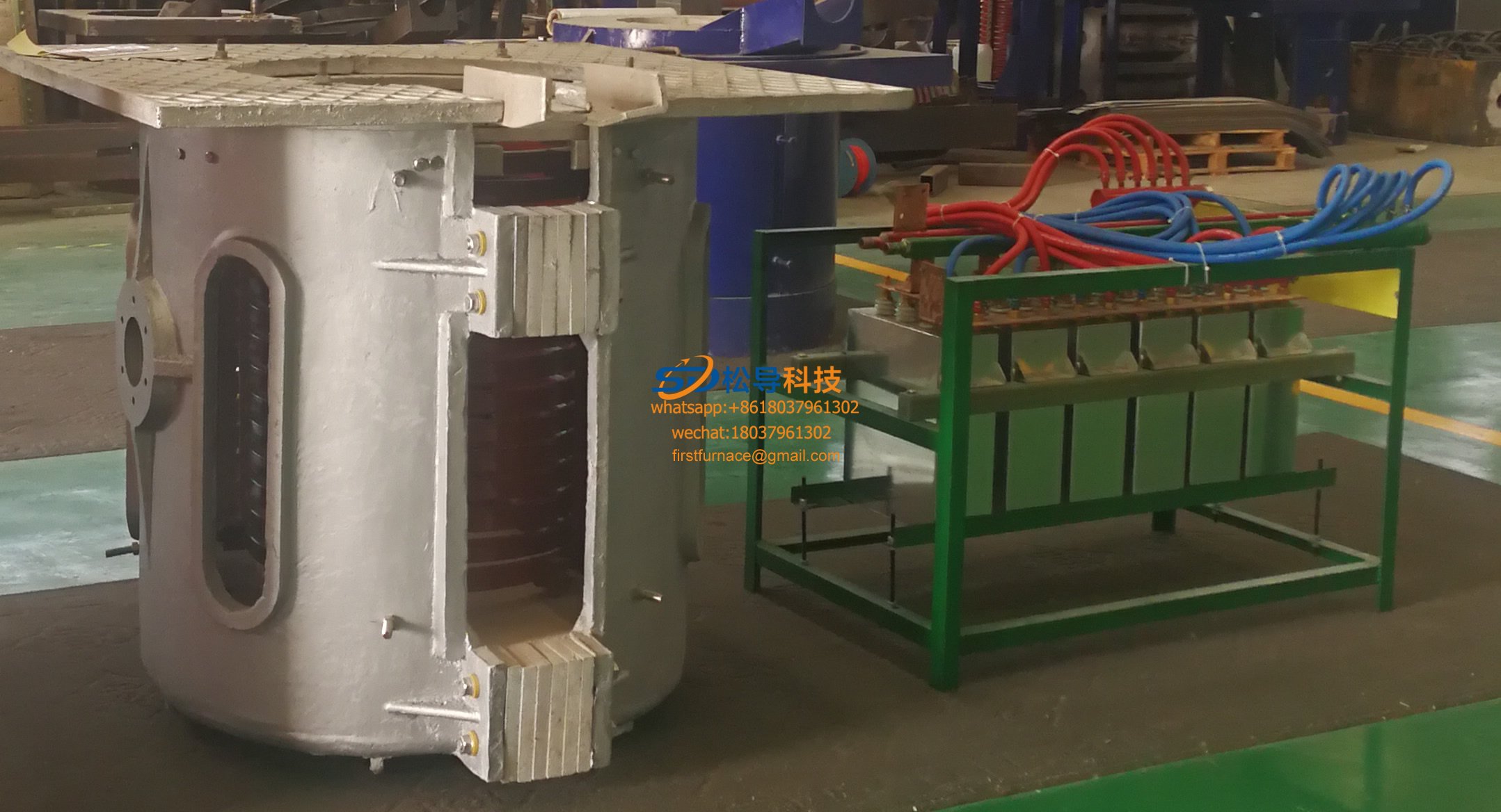
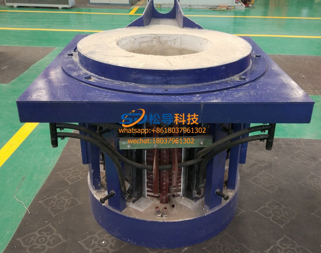
1T intermediate frequency aluminum melting furnace new inverter circuit debugging a good way
After the rectifier circuit is properly calibrated, the 1T medium frequency aluminum melting furnace restores the load terminal wiring of the inverter, checks whether the load connection is intact, compensates whether the capacitor insulation is reliable, and whether the induction coil has short circuit between the turns and short circuit to the ground. Turn on the three-phase AC power and control the power switch.
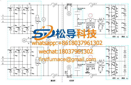
1 , 1T medium frequency aluminum melting furnace inverter circuit check inverter pulse
Turn the check switch on the control panel to his amp, use the synchronous oscilloscope to observe whether the pulse on the inverter thyristor is normal, and whether the diagonal thyristor pulse angle is the same. The two sets of pulses are 180 ° out of each other , and the pulse amplitude should be about 6V . . After the check is normal, the check switch is turned back to the self-excited gear, and the trigger pulse on the inverter thyristor should be clutter. The oscilloscope probe is connected to the control pole and cathode of the inverter thyristor, and the oscilloscope is placed in internal synchronization. After turning on the control power, you can see the inverter trigger pulse. It is a series of sharp pulses, the amplitude should be greater than 2V . Read the pulse period through the time scale of the oscilloscope to calculate the trigger pulse frequency. Normally, it should be higher than the nominal frequency of the power supply. About 20% , this frequency is called the starting frequency. When the start button is pressed, the pulse interval is increased, the frequency becomes lower. When it is normal, it should be about 40% lower than the nominal frequency of the power supply . Press the stop button and the pulse frequency will jump back immediately. Start frequency.
2 , 1T medium frequency melting aluminum furnace inverter loop calibration frequency table
Use an oscilloscope to detect the excitation frequency of the inverter trigger pulse (the excitation frequency can be adjusted by the frequency potentiometer), and adjust the frequency meter's trimming potentiometer so that the frequency meter reading is consistent with the measured value.
3 , 1T medium frequency melting aluminum furnace inverter circuit starting vibration inverter
Adjust the frequency trimming potentiometer on the control board to make it slightly higher than the resonant frequency of the circuit. The excitation and white-excitation trimmer potentiometers are rotated in the middle position. Turn the "given" potentiometer on the panel slightly clockwise, then the frequency starts to scan and the inverter bridge enters the working state. When the startup is successful, the voltage indicator on the control panel will go out.
The "given" potentiometer can be rotated and rotated repeatedly, so that the excitation signal is also repeatedly scanned. If the vibration is not stabilized, the phase of the intermediate frequency transformer can be adjusted. The debugging of this step can make the power switch of the control board in the OFF position. At this time, the repeating start function is added and the voltage loop is put into operation.
After the inverter starts to oscillate, the setting of the inverter lead angle can be performed. The inverter power control switch is set to the ON position, and the intermediate frequency voltage is adjusted to adjust the potentiometer so that the ratio of the intermediate frequency voltage to the DC voltage is 1.2.
about. Then turn the inverter power control switch to the OFF position and adjust the intermediate frequency voltage to trim the potentiometer so that the ratio of the intermediate frequency voltage to the DC voltage is about 1.5 (or higher). This debugging can be done at a lower intermediate frequency.
When adjusting the ratio of IF voltage to DC voltage, you must first adjust the relationship by 1.2 times and then adjust the relationship by 1.5 times. Otherwise, the order will be reversed, and there will be problems affecting each other. Set the voltage outer ring under light load, the power switch on the control board is turned to the OFF position, the intermediate frequency voltage trimming potentiometer is turned clockwise to the maximum, and the “given” potentiometer is rotated clockwise to make the inverter bridge work. Continue to turn the "given" potentiometer clockwise to the maximum, counterclockwise to adjust the intermediate frequency voltage trimmer potentiometer, so that the output of the intermediate frequency
The voltage reaches the rated value. If the slowly rotating "given" potentiometer, not IOOA over the direct current intermediate frequency sounds, the transformer can ( LH5) lead terminal ( " 111 ", " 112 " ) is reversed or transformer (B2) secondary end lead ( " 110 ", " 111 " ) isreversed, so mobilized several times, should start normally. Repeatedly start several times to observe whether the DC voltage, DC current, IF voltage, and IF power meter reading are normal. If not, adjust the IF voltage trimmer potentiometer and the “given” potentiometer so that the ratio of IF voltage to DC voltage is 1.3 or so. In this debugging, it can be seen that the impedance regulator works, that is, the DC voltage no longer rises, and the intermediate frequency voltage can continue to rise with the rotation of the "given" potentiometer.
DC voltage jitter may occur during debugging, and the intermediate frequency power reactor emits an irregular impact sound. The oscilloscope can observe that the filtered voltage waveform has irregular jitter. The reason is:
(1) The control board of the thyristor enters the interference signal, which is caused by the voltage jump generated when the thyristor of the intermediate frequency power supply is turned off and turned on. These abrupt voltages are infiltrated into the thyristor control board through circuit coupling or space, causing the thyristors to be mis-conducted. In this case, check all components of the rectifier trigger circuit to see if it is damaged or desoldered and to enhance the filtering of the rectified trigger power supply.
(2) The rectification trigger pulse has a pulse width at a critical value, and detects whether the supplemental pulse and the original pulse are lost.
4 , 1T medium frequency aluminum melting furnace inverter loop startup link debugging
The steps for debugging the startup link are as follows:
(l) Switch the inspection and work switch to the "working" state and the inverter switch to the "off" position.
(2) Press the inverter switch to see if the DC voltage displayed on the DC voltmeter is about 100V . If not, adjust it to about 100V . After normal, see if the DC voltage reaches 400V after 3s . If the voltage reaches 400V , it means that the full load power starts, and the voltage needs to be corrected back to 400V .
The above debugging work is normal, indicating that the intermediate frequency power supply pre-charging link meets the requirements, otherwise the charging circuit needs to be checked.
5 , 1T medium frequency aluminum melting furnace inverter circuit overvoltage protection adjustment
After the intermediate frequency power supply is started, the intermediate frequency voltage is raised to 1.2-1.3 times of the rated output voltage of the inverter, and the overvoltage precision potentiometer is adjusted to make the overvoltage protection circuit operate, and the overvoltage indicator on the control cabinet door is illuminated, repeating several times without errors. Just fine.
Iron induction furnace
Aluminum melting furnace
Copper melting furnace
Small steel melting furnace
Small induction melting furnace
Induction iron furnace
3T intermediate frequency iron melting f

0.25T Intermediate Frequency Furnace

0.5T Intermediate Frequency Furnace

Medium Frequency Furnace

2T Induction Melting Furnace

1T Induction Melting Furnace

500kg Induction Melting Furnace

250kg Induction Melting Furnace

Induction Melting Furnace

3 T Induction Melting Furnace

5T Induction Melting Furnace
1T One Belt Two Intermediate Frequency F

5T One Belt Two Intermediate Frequency F
3T One Belt Two Intermediate Frequency F
2T One Belt Two Intermediate Frequency F
5T Parallel Intermediate Frequency Furna

5T Intermediate Frequency Furnace

5T Series Intermediate Frequency Furnace
3T Series Intermediate Frequency Furnace
2T Series Intermediate Frequency Furnace
1T Series Intermediate Frequency Furnace
0.5T Series Intermediate Frequency Furna

0.25T Series Intermediate Frequency Furn
1T Parallel Intermediate Frequency Furna
2T Parallel Intermediate Frequency Furna
0.5T Parallel Intermediate Frequency Fur