Sales hot line ( 24 hours service): 18037961302
E-Mail: firstfurnace@gmail.com
whatsapp:+8618037961302
Adress: Luoxin Industrial Park, Luoyang, HenanLarge diameter steel pipe quen
Piston rod quenching and tempe
Grinding rod quenching and tem
High frequency induction heate
Quenching equipment for machin
Round steel end heating furnac
Steel pipe heat treatment prod
Square steel quenching and tem
Sucker rod quenching and tempe
Thickened petroleum steel pipe
Round steel quenching and temp
Steel pipe quenching and tempe
Steel plate quenching and temp
Induction Hardening Machine&nb
Flywheel ring gear high freque
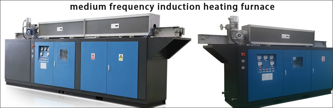
Tubing end induction heating equipment
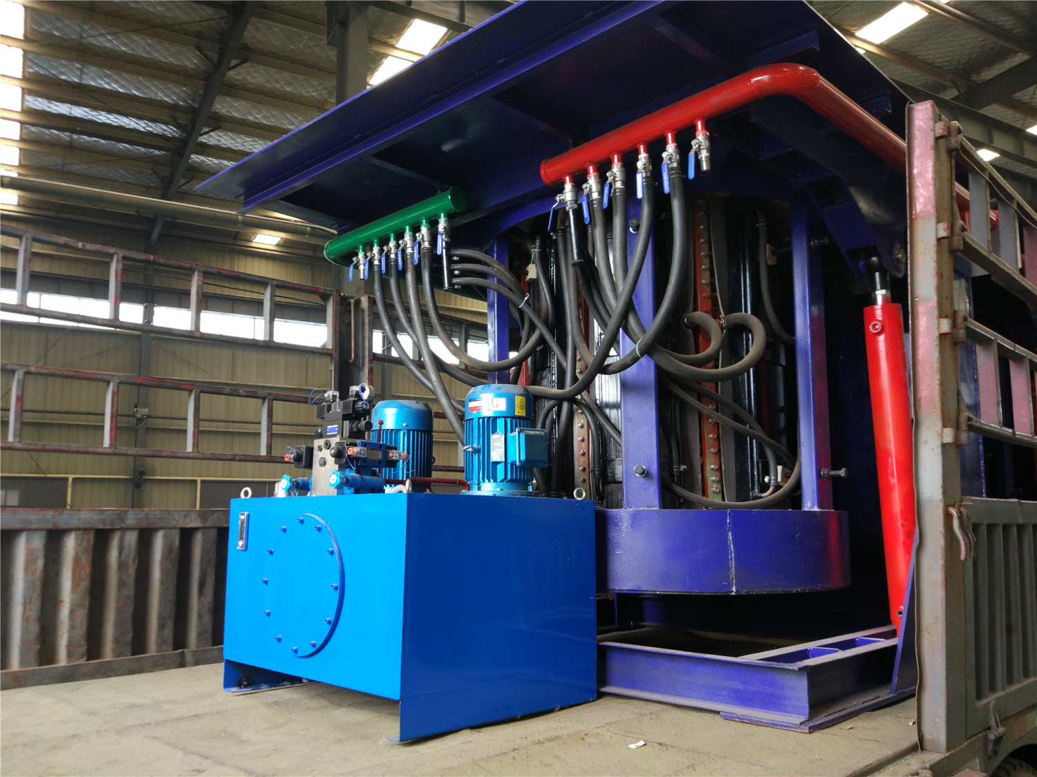
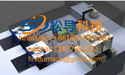
1. The composition of the induction heating device at the end of the tubing
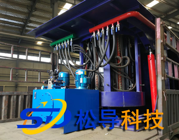
The tubing end induction heating equipment consists of medium frequency induction heating furnace, capacitor cabinet, trolley, hydraulic cylinder, water pack, trolley, stainless steel towline, water and electric oil pipeline and intermediate frequency power cabinet.
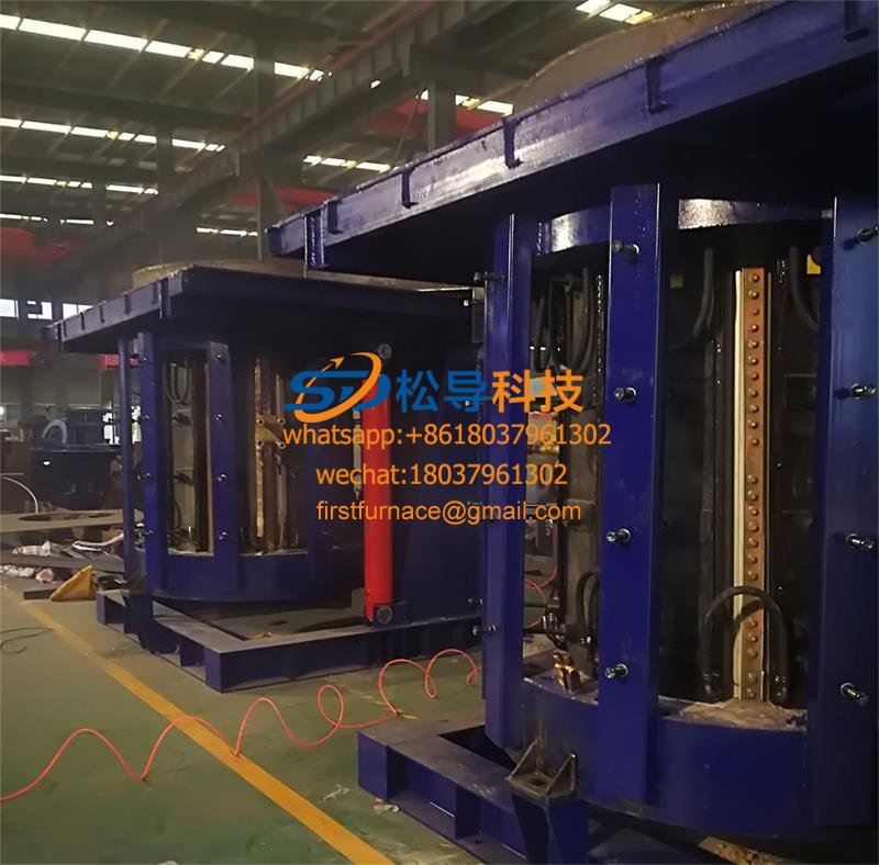
This set of equipment has two trolleys, each of which is placed on a rail laid on the ground, driven by human power, and has a positioning screw device. There is a small car on each trolley. The chassis of the trolley is welded by angle steel, and the small wheel is aV -shaped groove wheel to ensure the smooth movement of the trolley. The chassis of the car is equipped with a worm lifter, and a large bottom plate made of an epoxy plate is fixed on the lifter. To ensure the smooth rise and fall of the large floor, the large floor and the car chassis are positioned by linear slide rails. A medium-frequency induction heating furnace is installed at each end of the large bottom plate. The trolley can be moved forward and backward along the track fixed on the trolley under the push of the cylinder. The intermediate frequency induction heating furnace is fixed on the small bottom plate by four bolts. The large bottom plate can be raised or lowered by the manual lifter, and the small bottom plate can pass through the wire. The rod moves left and right to adjust the center of the intermediate frequency induction heating furnace in the working position. Each IF induction furnace is equipped with a capacitor cabinet. The capacitor cabinet is fixed on the trolley, and the capacitor cabinet is connected with the medium frequency induction heating furnace through a water-cooled cable. One end of the water and oil pipeline is connected to the equipment on the trolley, and the other end is connected to the water supply pipe joint in the intermediate frequency power cabinet and the trench. The connection between the capacitor cabinet on the trolley and the intermediate frequency induction heating furnace and the water and oil connection between the trolley and the ground are respectively installed in the stainless steel towline.
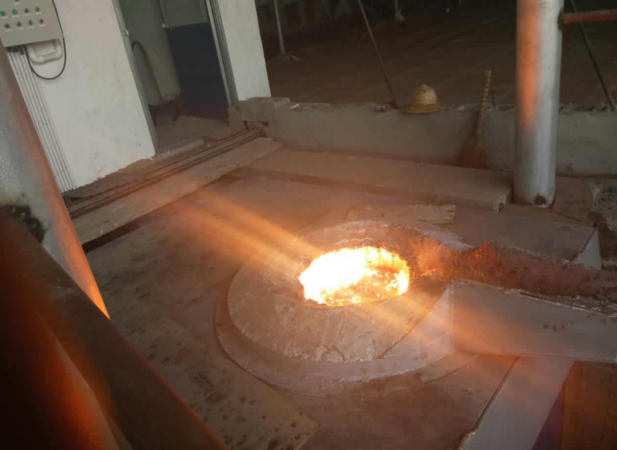
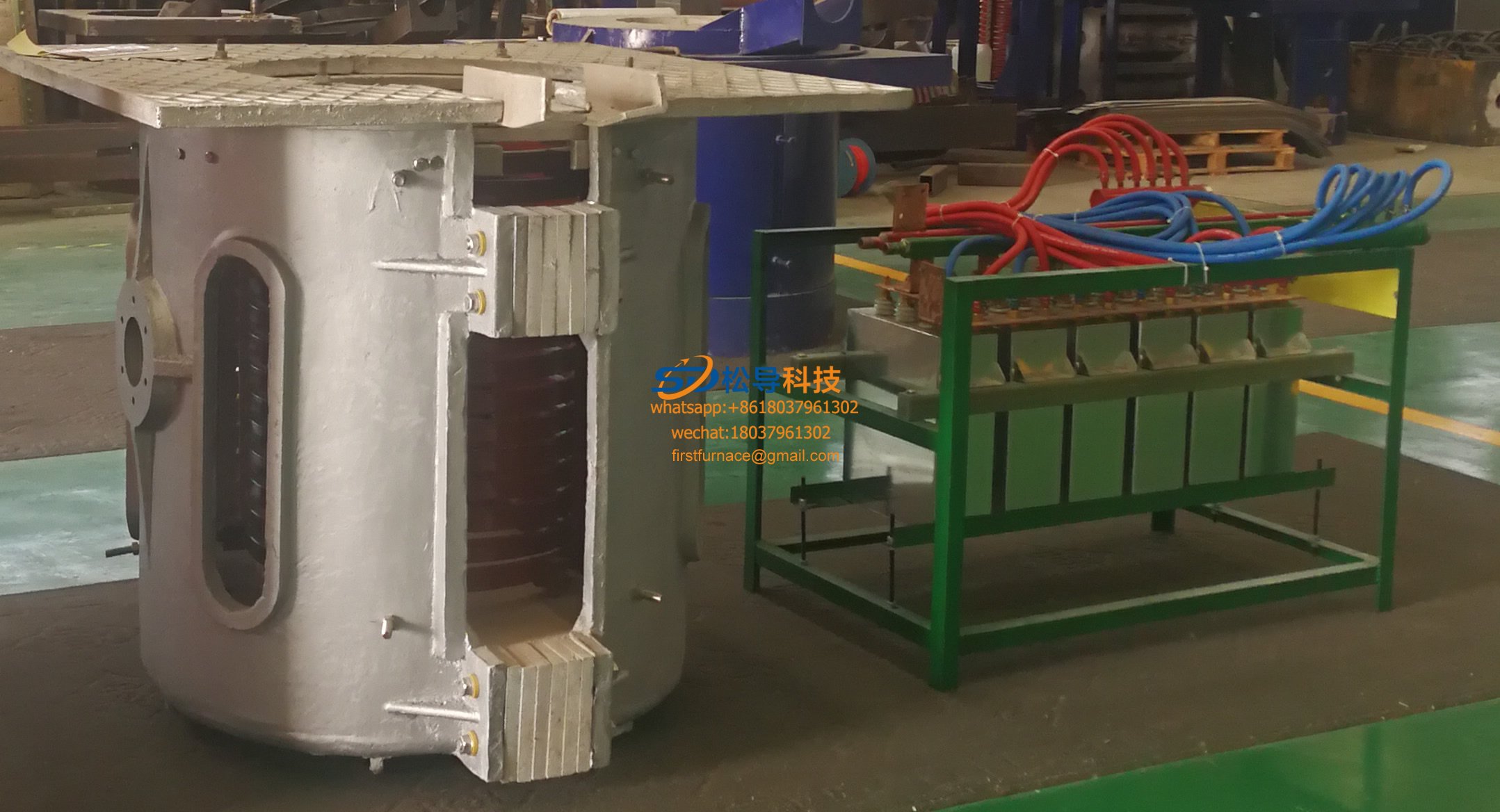
2, the structure, function and working principle of the oil pipe end induction heating equipment
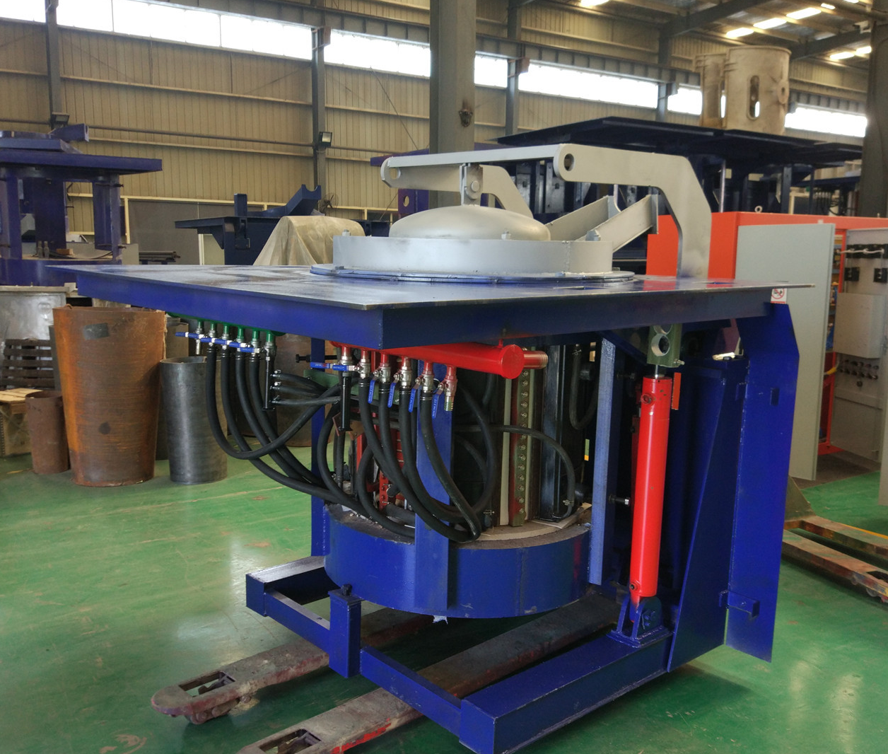
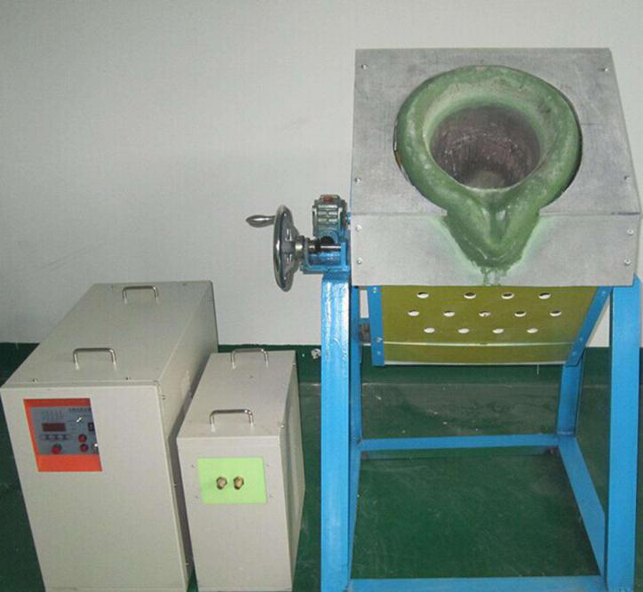
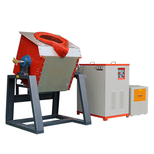
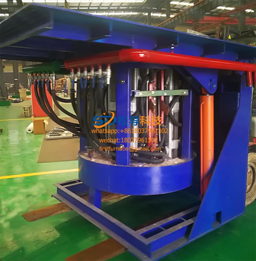
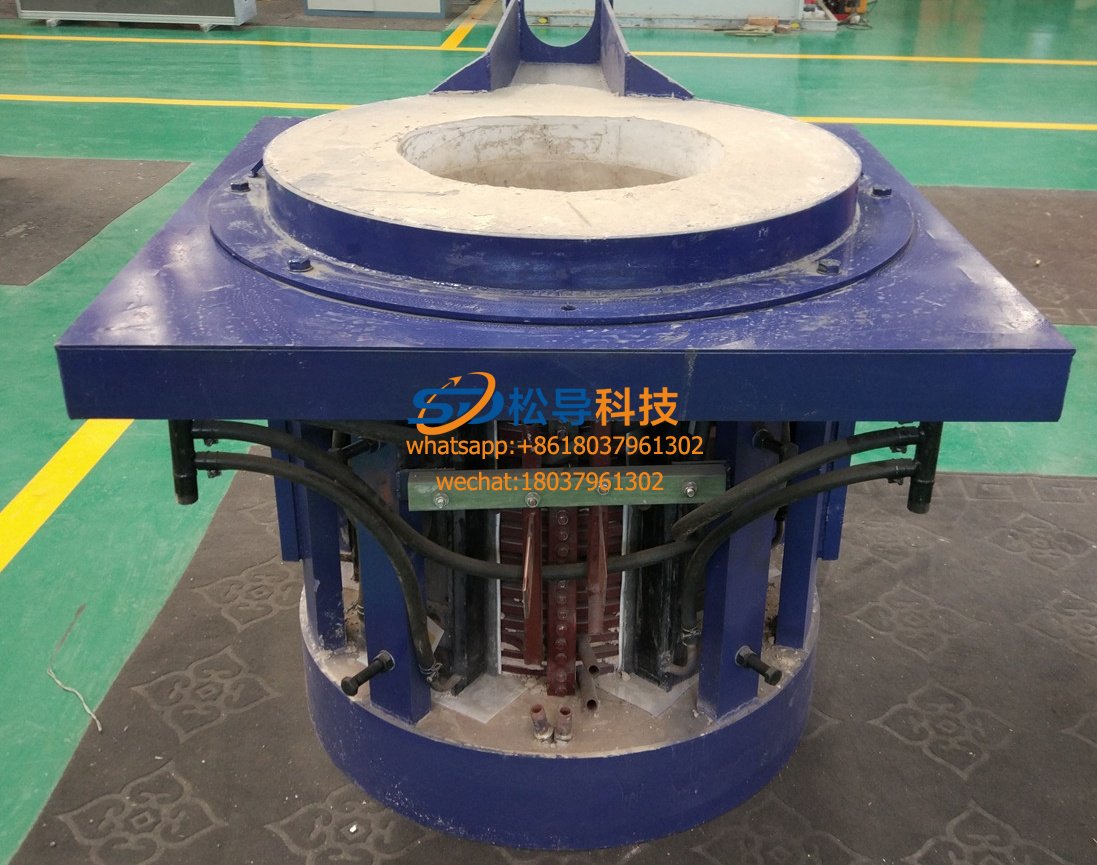
, The principle of induction heating of the workpiece is heated by the heat generated in the workpiece itself by electromagnetic induction, this has the heating fast heating, uniform heating, high heating efficiency, and very little oxidation process reproducibility, etc., which The medium frequency induction heating furnace is widely used in the pressure processing of metal materials and the heating process of heat treatment. The medium frequency induction heating furnace is composed of an induction coil, a furnace lining, a supporting fixed structure and a furnace shell. The induction coil is made of a copper tube with a rectangular cross section. The copper tube is cooled by water during operation; the support structure and the furnace shell are made of non-metallic materials with high strength, high temperature resistance and non-flammability.
This equipment total power 180kw and 220kw two kinds of specifications 16 16 station frequency induction furnace to meet different specifications of the ends of the heating pipe. No. 1 No. 1furnace carriage and No. 2 furnace power and 180kw respectively 220kw, No. 2 No. 3furnace carriage and 4 respectively furnace power is 180kw and 220kw. The center distance of the two IF induction furnaces on each trolley is 1200 mm and the center is 1000 mm above the ground . Each of the four furnaces is equipped with its own intermediate frequency power cabinet and capacitor cabinet. The 16 IF induction furnaces have the same dimensions and mounting interfaces to ensure that the IF induction furnace can be replaced quickly . ,
3, the technical parameters of the medium frequency induction heating furnace for the end heating of the oil pipe
|
|
No. 1 trolley |
No. 2 trolley |
Remarks
|
||
|
No.1heating furnace |
No 2 heating furnace |
No.3heating furnace |
No.4 heating furnace |
||
|
Power(kw) |
180 |
220 |
180 |
220 , |
|
|
Frequency (khz) |
1.0 |
2.5 |
1.0 |
2.5 |
|
|
Heating temperature (°C) |
Room temperature ~750 |
700to1250± 10 |
450~850 |
800to1250±10 |
|
|
Cooling water volume (m3/h) |
15 |
15 |
15 |
15 |
External circulation water |
|
Cooling water pressure (Mpa) |
0.1to0.4 |
0.1 to 0.4 |
0.1 to 0.4 |
0.1 to 0.4 |
|
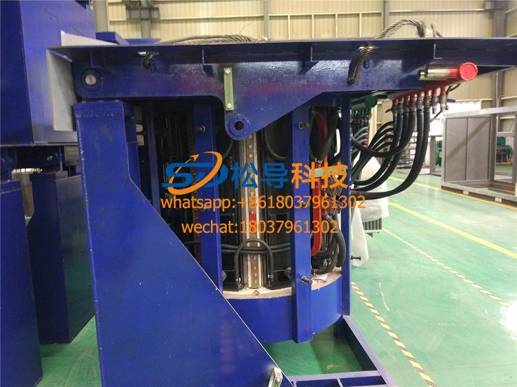
4, the end of the tubing heating car
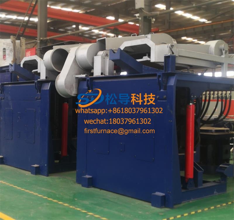
The trolley consists of an angle steel chassis with four slotted wheels and two upper and lower epoxy panels (silk plates). The upper plate is a small bottom plate with a thickness of 20 mm, and the lower plate is a large bottom plate with a thickness of 25 mm. The small bottom plate is mounted on the sliding shaft, and the sliding shaft is fixed on the large bottom plate. The lower part of the small bottom plate is provided with a nut, and the rotating screw can move the small bottom plate laterally. The large bottom plate is fixed to the worm lifter mounted on the chassis of the cart and is positioned by four linear slide rails. The lifter controls the large bottom plate to move up and down, and the small bottom plate moves up and down, so that the center of the sensor can be adjusted as required. A stainless steel bracket for fixing the drag chain is attached to the rear side of the lower panel, and the drag chain is fixed at the upper end of the bracket. The base of the trolley is welded with a support base connected to the oil cylinder, and under the action of the oil cylinder, the trolley can move forward and backward along the track. In this way, the intermediate frequency induction heating furnace mounted on the upper deck can adjust the position in the three-dimensional direction as required. The up and down and left and right trimming movements are manual, the front and rear movements are pushed by the cylinder, the stroke is controlled by the proximity switch, and the stroke length can be displayed on the scale fixed on the trolley. ,
5, the end of the tubing heating cylinder
The bore is φ 63 mm and the maximum stroke is 600 mm. The tubing and its accessories are selected from Guangzhou Agate Company. The cylinder is fixed on the trolley surface. The oil pipe is connected to the inlet and outlet oil pipes in the trench through the drag chain.
Water bag group
The water bag group is located at the rear and both sides of the trolley. Its function is to transport and collect cooling water to the two intermediate frequency induction heating furnaces and the two capacitor cabinets on the trolley. The cooling water of the intermediate frequency induction heating furnace is driven into the two furnaces by the water pump and the water separator of the large water bag group. After the furnace comes out, it enters the water collector of the large water bag group, and passes through the water outlet and the pipeline. Finally, it flows back to the circulating pool. It belongs to the open loop. The electric contact pressure gauge is installed on the water separator of each intermediate frequency induction heating furnace. When the water pressure is lower than the working pressure, the furnace is automatically powered off, and the equipment will not be damaged due to the water shortage of the coil. The cooling water of the capacitor cabinet comes from the soft water of the cooling unit, and enters the two capacitor cabinets through the water separator of the small water pack group, and then flows back to the water collector of the small water pack group, and finally returns to the cooling unit. It is a closed loop. The inlet and outlet of the two water packs are respectively connected to the inlet and outlet ports in the trench through the hoses in the drag chain.
All influent water is fitted with valves at the water pipe joints in the trench.
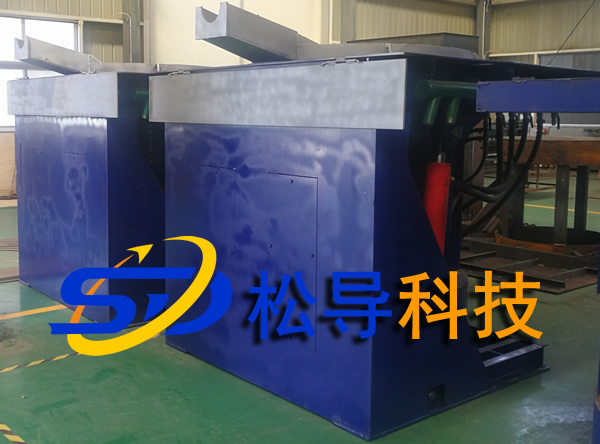
6, the end of the tubing heating set trolley
The trolley is the main body of the load, and the main equipment is installed on the trolley. The size of the trolley is 2700 * 1900 mm 2 and the surface of the trolley is about 366 mm above the ground . The trolley is driven by humans and the stroke is not less than 2800mm. After the trolley is in place, the four screws are unscrewed to position the trolley. ,
7, the end of the tubing heating is set with stainless steel towline
In order to ensure the synchronization and safety of the pipeline in the movement of the trolley and the trolley, all the nozzles on the trolley and the ground connection (including the hydraulic hose) are connected by a drag chain, the trench end is a fixed end, and the trolley end is a movable end. The trench - trailer stainless steel towline is TL125 III -300*350 .
The water-cooled cable between the capacitor cabinet on the trolley and the intermediate frequency induction heating furnace is also connected by a drag chain. The capacitor cabinet end is a fixed end, and the intermediate frequency induction heating furnace end is a movable end. Capacitor cabinet - medium frequency induction heating furnace stainless steel towline specification is TL95 III -150*250 . At the same time, the cooling water hose that enters and exits the medium frequency induction heating furnace from the large water bag is also installed in the drag chain.
8, tubing end heating installation and maintenance
1. Before replacing the medium frequency induction heating furnace, stop the power and stop the water before removing the water-cooled cable snail.
Quickly change the joint between the bolt and the water pipe. After the heating furnace is replaced, test the water leak first, and confirm that the joint does not leak water before it can be energized;
2 , often check the drag chain for stuck or dropped chains;
3 , keep the circulating pool clean and free of debris, so as to prevent debris from entering the pipeline and causing blockage.
Random material
Product qualification certificate;
Product supply list;
Packing List;
Instruction Manual;
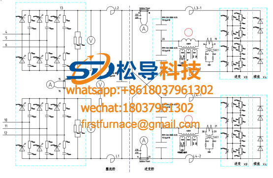
Electrical schematic and instructions;
Random supply drawings:
Trench piping layout;
General diagram of the heating machine;
Power and furnace layout.
Iron induction furnace
Aluminum melting furnace
Copper melting furnace
Small steel melting furnace
Small induction melting furnace
Induction iron furnace
3T intermediate frequency iron melting f

0.25T Intermediate Frequency Furnace

0.5T Intermediate Frequency Furnace

Medium Frequency Furnace

2T Induction Melting Furnace

1T Induction Melting Furnace

500kg Induction Melting Furnace

250kg Induction Melting Furnace

Induction Melting Furnace

3 T Induction Melting Furnace

5T Induction Melting Furnace
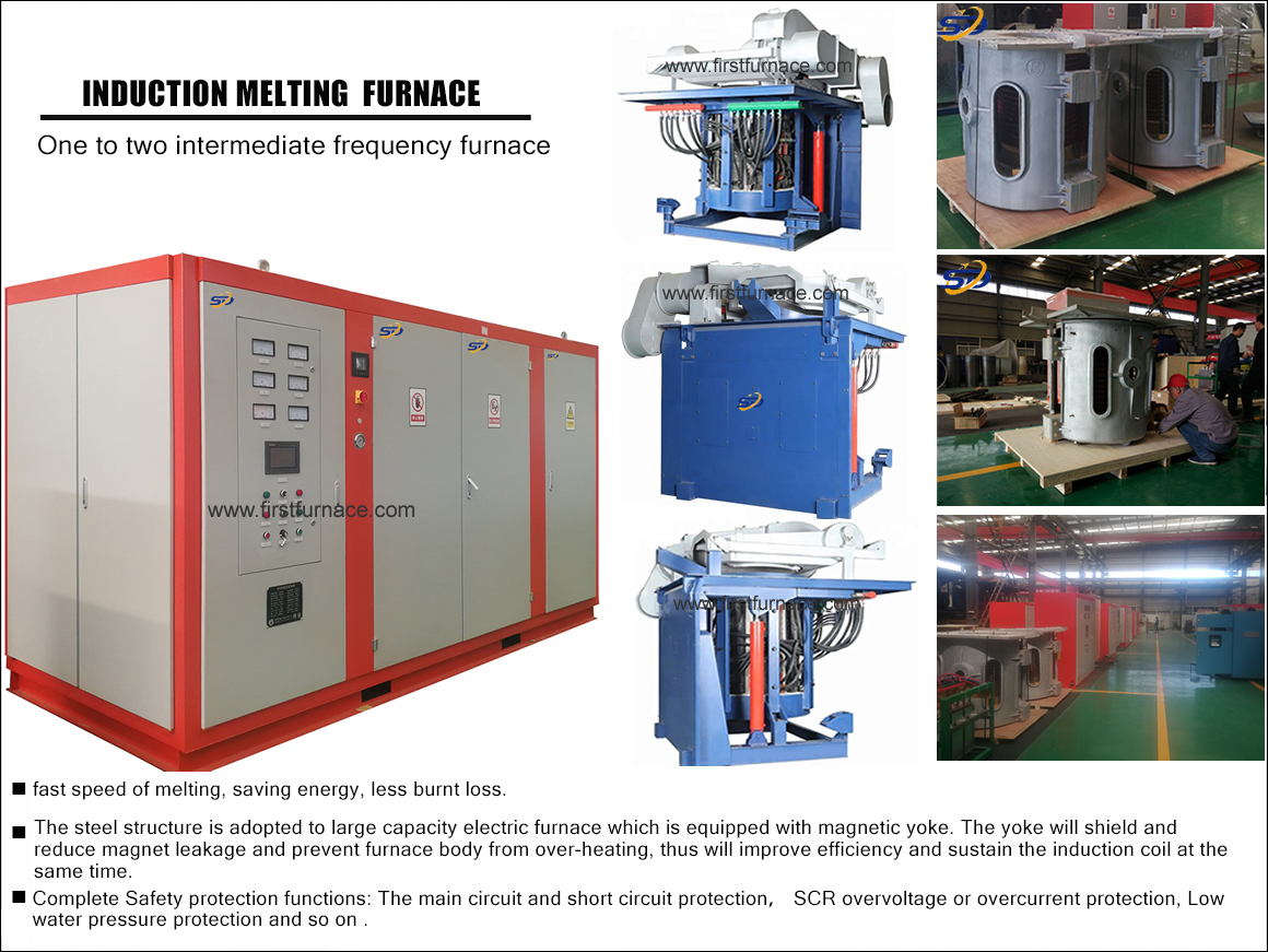
1T One Belt Two Intermediate Frequency F

5T One Belt Two Intermediate Frequency F
3T One Belt Two Intermediate Frequency F
2T One Belt Two Intermediate Frequency F
5T Parallel Intermediate Frequency Furna

5T Intermediate Frequency Furnace

5T Series Intermediate Frequency Furnace
3T Series Intermediate Frequency Furnace
2T Series Intermediate Frequency Furnace
1T Series Intermediate Frequency Furnace
0.5T Series Intermediate Frequency Furna

0.25T Series Intermediate Frequency Furn
1T Parallel Intermediate Frequency Furna
2T Parallel Intermediate Frequency Furna
0.5T Parallel Intermediate Frequency Fur