Contact
Tel: 18037961302
Sales hot line ( 24 hours service): 18037961302
Sales hot line ( 24 hours service): 18037961302
E-Mail: firstfurnace@gmail.com
whatsapp:+8618037961302
Adress: Luoxin Industrial Park, Luoyang, HenanLarge diameter steel pipe quen
Piston rod quenching and tempe
Grinding rod quenching and tem
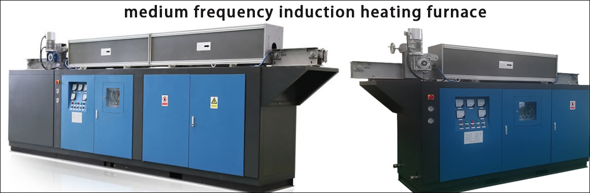
High frequency induction heate
Quenching equipment for machin
Round steel end heating furnac
Steel pipe heat treatment prod
Square steel quenching and tem
Sucker rod quenching and tempe
Thickened petroleum steel pipe
Round steel quenching and temp
Steel pipe quenching and tempe
Steel plate quenching and temp
Induction Hardening Machine&nb
Flywheel ring gear high freque
Electric furnace principle(原理)
Fourteen fault repair methods for induction melting furnace
Preparation before maintenance
1. The tools needed for maintenance are: multimeter, double trace oscilloscope above 20M, electric soldering iron, screwdriver, wrench, etc.
2. The documents required for maintenance include: technical documents such as equipment-related electrical drawings and manuals.
3. Before repairing, you should first understand the failure phenomenon of the equipment, what happened when the failure occurred, and check the record data of the equipment.
4. Prepare some vulnerable and commonly used components.
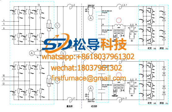
1. The induction melting furnace equipment cannot be started. When starting, only the DC ammeter has indications, but the DC voltage and intermediate frequency voltmeters have no indication. ⑥⑦⑧ Failure analysis and treatment: This is one of the most common failure phenomena, and the cause may be:
①. There is a lack of pulse in the inverter trigger pulse-check the inverter pulse with an oscilloscope (preferably on the AK of the thyristor). If there is a lack of pulse phenomenon, check whether the connection has poor contact or open circuit. Whether there is pulse output.
②. Inverter thyristor breakdown-replace the thyristor and check the reason for the damage of the thyristor (for the reason of the thyristor damage, please refer to the following analysis of the reason for the damage of the thyristor).
③. Capacitor breakdown-remove the damaged capacitor pole.
④ The load has short-circuit and grounding phenomena-eliminate short-circuit points and grounding points.
⑤ There is an open circuit or short circuit in the sampling circuit of the intermediate frequency signal-use an oscilloscope to observe the waveform of each signal sampling point, or use a multimeter to measure the resistance value of each signal sampling circuit when it is not powered on, and find the open or short circuit point.
2. It is difficult to start. After starting, the intermediate frequency voltage is twice as high as the DC voltage, and the DC current is too large. Failure analysis and treatment: the reasons for this failure are:
① One thyristor in the inverter circuit is damaged-when a thyristor in the inverter circuit is damaged, the equipment can sometimes be started, but the above-mentioned failure phenomenon will occur after starting, replace the damaged thyristor and check the damage the reason.
② There is an open circuit or wrong polarity in the sampling circuit of the intermediate frequency signal-this reason is mostly in the line that adopts the angle method. Open circuit of the intermediate frequency voltage signal or reverse the polarity of the intermediate frequency voltage signal when repairing other faults will cause This failure phenomenon.
③, the front angle shift circuit of the inverter fails-the load of the intermediate frequency power supply is capacitive, that is, the current leads the voltage. In the sampling control circuit, a phase shift circuit is designed. If the phase shift circuit fails, it will also cause this malfunction.
3. It is difficult to start. After starting, the DC voltage can only rise to 400V, and the reactor vibrates loudly and the sound is dull. Fault analysis and treatment: This kind of fault is a three-phase fully-controlled rectifier bridge fault. The main reasons are:
① Open circuit, breakdown, soft breakdown of the rectifier SCR or performance degradation of electrical parameters-use an oscilloscope to observe the tube voltage drop waveform of each rectifier SCR, find the damaged SCR and replace it. When the damaged thyristor breaks down, the voltage drop waveform of the tube becomes a straight line; when the voltage rises to a certain value during soft breakdown, it becomes a straight line; when the electrical parameter drops, the waveform changes when the voltage rises to a certain value. If the above phenomenon occurs, the DC current will be cut off, causing the reactor to vibrate.
②. Lack of a set of rectifier trigger pulses-use an oscilloscope to check each trigger pulse (preferably on the SCR). When the circuit without pulse is checked, use the backward method to determine the fault location and replace the damaged device. When this phenomenon occurs, the output wave head of the DC voltage will lack a wave head, causing the current to cut off, resulting in this failure phenomenon.
4. It can be started, but it stops immediately after starting, and the equipment is in a state of repeated starting. Failure analysis and treatment: This type of failure is a device failure in the sweep-frequency startup mode, and its reasons are:
①. The front angle of the inverter is too small, and repeated starts due to the failure of commutation after starting-Use an oscilloscope to increase the front angle of the inverter by observing the intermediate frequency voltage waveform.
②. The load oscillation frequency signal is at the edge position of its excitation scanning frequency signal range-readjust the scanning range of its excitation scanning frequency.
5. After the induction melting furnace equipment is started, when the power rises to a certain value, the equipment overcurrent protection will act. Sometimes the thyristor components will be burned out and restarted, the phenomenon remains the same. Failure analysis and treatment:
This failure phenomenon is generally caused by the following two reasons:
①. Water cut in the water cooling jacket of the inverter thyristor or reduced heat dissipation effect-replace the water cooling jacket. Sometimes it is sufficient to observe the water output and pressure of the water-cooling jacket, but often due to water quality problems, a layer of scale is attached to the wall of the water-cooling jacket. Because the scale is an object with poor thermal conductivity, although there is enough water flow through, But because of the isolation of scale, its heat dissipation effect is greatly reduced. The judgment method is: run the power at a power lower than the overcurrent value for about ten minutes, and then shut down quickly. After shutting down, touch the core of the thyristor element with your hands quickly. If you feel hot, the fault is caused by Caused by this reason.
②. Poor contact and disconnection of the connecting wire of the tank circuit-check the connecting wire of the tank circuit and deal with it according to the actual situation. When the connecting wire of the tank circuit has poor contact or disconnection, the power will be sparked after the power rises to a certain value, which affects the normal operation of the equipment, which leads to the protection of the equipment. Sometimes due to ignition, instantaneous overvoltage will be generated at both ends of the thyristor. If the overvoltage protection action is too late, the thyristor element will be burnt out. This phenomenon often occurs at the same time as over-voltage and over-current.
6. There is no response when the device is started. After observation, the lack of phase indicator on the control circuit board is on. Failure analysis and treatment:
This failure phenomenon is more obvious and is caused by the following reasons:
① Fast fuse blown――Generally fast fuse has a fuse indication, you can judge whether the fuse is blown by observing the indication, but sometimes due to the long use of the fast fuse or quality reasons, no indication or unclear indication , It must be measured with a multimeter after power off. The treatment method is: replace the fast fuse and analyze the cause of the blow. Generally, there are two reasons to blow the fast fuse: The equipment runs under the condition of high power and high current for a long time, which causes the fast fuse to heat up, which causes the fuse core to melt. The failure of the rectifier control circuit caused an instantaneous high-current shock wave. The rectifier circuit should be checked. The rectifier load or the intermediate frequency load is short-circuited, causing an instantaneous high current impact and burning the fast fuse. Check the load circuit.
②. The contact of the master switch is burnt out or the front-level power supply system has a phase-missing fault-use the AC voltage file of a multimeter to measure the line voltage of each level to determine the location of the fault.
7. When the equipment is running, the DC current can reach the rated value, but the DC voltage and the intermediate frequency voltage are low. Observe the intermediate frequency voltage waveform with an oscilloscope. The waveform is normal and the inverter lead angle is also normal. Fault analysis and treatment: This fault phenomenon does not belong to an intermediate frequency power supply failure, but is caused by the impedance of the load being too low, and the load impedance must be readjusted.
①. In the circuit of boost load, because the series-connected compensation capacitor is damaged, it is removed without replacement, or the compensation capacitor is added uncontrollably while seeking high power, which will cause the compensation of the load to be over-compensated. Failure phenomenon. The solution is to re-adjust the compensation amount of the compensation capacitor so that the equipment can operate at the rated power.
② The inductor has an inter-turn short-circuit phenomenon-if the inductor has an inter-turn short-circuit phenomenon, the impedance of the load will also decrease, causing this failure phenomenon. There are two possibilities for short-circuit between turns: The copper tube of the inductor is directly short-circuited. The fixed bakelite column of the sensor is severely carbonized. Due to the conductive properties of the carbon, the carbonized bakelite makes the turn of the inductor directly connected to the turn, which causes a short circuit between the turns of the inductor. The solution is to eliminate the inter-turn short-circuit phenomenon.
8. When the equipment is running, both the DC voltage and the intermediate frequency voltage should reach the rated value, but the DC current is small and the power is low. Failure analysis and treatment: This failure phenomenon is opposite to the cause of the "8.2.7" failure phenomenon, and is caused by the high load impedance.
① The compensation amount of the load compensation capacitor is insufficient-increase the compensation capacitor.
②. The node contact resistance of the connecting wire of the tank circuit (load LC oscillating circuit) is too large-due to the long-term use of the equipment, the connection of the tank circuit copper bar is affected by dust, which increases the contact resistance and causes the load The impedance increases, and this failure phenomenon occurs.
9. The equipment is operating normally, and the DC current indication is too high. If the current is set at the rated value, the voltage is too low, and the indication value of the power meter does not match the DC voltage and DC current sum product, which was consistent before. Failure analysis and treatment:
This failure phenomenon is somewhat similar to the "seven" failure phenomenon, but there are differences. The reason for the failure is that the indication of the DC ammeter is not accurate, which gives people an illusion that the current is large. The cause of this failure is relatively hidden and difficult to find at the moment. If you analyze carefully, you can find that the indicated value of power does not match the product of voltage and current, indicating that the displayed value of the meter may be wrong. The voltage value can be calibrated by the DC voltage file of the multimeter, and the current value can be calibrated by measuring the incoming line current with a clamp ammeter and then multiplying it by 0.816. If it does not match, the indication of the ammeter is inaccurate. The value of the DC ammeter is taken from the 75mV voltage signal generated on the shunt. Under the conditions of long use time and harsh environment, there is dirt or oxidation between the wiring on the shunt and the shunt, and the contact resistance increases. , So that the voltage generated on the shunt is increased to more than 75mV, which causes the indication of the DC ammeter to be too large. The treatment method is: treat the dirt and oxide layer between the shunt and its wiring.
10. The induction melting furnace equipment is operating normally, but there is no response after shutdown, and there is no protection indication. Failure analysis and treatment: There are two possibilities for this type of failure:
①. The intermediate frequency start switch is broken-the intermediate frequency start switch is in the grounding state (connected to the closed point of the switch) when the intermediate frequency is stopped. If the switch is broken, the grounding state cannot be opened, and the device is in the protection state, so there is no response when starting. Solution: Replace the intermediate frequency start switch.
②, protection circuit failure-for example, refer to the "control circuit schematic diagram", the integrated circuit IC4 heating during operation will cause this failure. Treatment method: heat the IC4 integrated circuit or add a heat sink. ③. In the given circuit, the given signal is interrupted-in the given circuit, an open circuit somewhere during the signal given process makes it impossible to shift the phase of the rectified pulse, which can also cause this malfunction. Processing method: use the backward method to check the given circuit.
11. Frequent burnout of thyristor components. After replacing the new thyristor, it will burn out immediately. Fault analysis and treatment: This is a troublesome phenomenon that makes it difficult to repair. SCRs are more expensive, but burnout of SCRs is hard to prevent, so be careful when repairing such failures. When we analyzed the fault "2.5", we introduced a reason for burning out the thyristor. In addition, there are the following reasons:
① When the anti-correlation of the thyristor is broken, the instantaneous glitch voltage of the reverse voltage is too high-in the main circuit of the intermediate frequency power supply, the instantaneous reverse glitch voltage is absorbed by the resistance-capacitance absorption. If the resistance and capacitance in the absorption circuit are open, the instantaneous reverse glitch voltage will be too high and the thyristor will be burned. In the case of power failure, use a Wanxiu meter to measure the resistance of the absorption resistance and the capacity of the absorption capacitance to determine whether the resistance-capacitance absorption circuit is faulty.
②, the insulation of the load to the ground is reduced-the insulation of the load circuit is reduced, causing the load to ignite between the load and the ground, which interferes with the trigger time of the pulse or forms a high voltage at both ends of the thyristor and burns the thyristor component.
③. Pulse trigger circuit failure-If the trigger pulse is suddenly lost when the equipment is running, the inverter will open, and high voltage will be generated at the output of the intermediate frequency power supply, which will burn out the thyristor components. This kind of fault is generally the formation of the inverter pulse and the output circuit failure, which can be checked with an oscilloscope. It may also be caused by poor contact of the inverter pulse lead. You can shake the wire connector by hand to find the fault location.
④. The load is open when the equipment is running-when the equipment is running at high power, if the load is suddenly open, it will form a high voltage and burn out the thyristor element at the output.
⑤ The load is short-circuited when the device is running-when the device is running at high power, if the load is suddenly in a short-circuit state, it will have a large short-circuit current impact on the thyristor. If the overcurrent protection action fails to protect it, it will burn Bad SCR components.
⑥ Protection system failure (protection failure)-whether the SCR is safe or not is mainly guaranteed by the protection system. If the protection system fails, the equipment does not work properly, which will threaten the safety of the SCR. Therefore, it is essential to check the protection system when the thyristor burns out.
⑦, Thyristor cooling system failure-the thyristor generates a lot of heat when it is working, and it needs to be cooled to ensure normal operation. Generally, there are two ways to cool the thyristor: one is water cooling, the other is Wind-cooled. Water cooling is widely used, and air cooling is generally only used for power equipment below 100KW. Usually the intermediate frequency equipment that adopts the water cooling method is equipped with a water pressure protection circuit, but it is basically the protection of the total water inlet. If a water block occurs in a certain road, it cannot be protected.
⑧ Reactor failure-the internal ignition of the reactor causes the current on the inverter side to be intermittent, and it will also produce high voltage on the inverter input side to burn out the thyristor. In addition, if the reactor is replaced during maintenance, and the inductance of the reactor and the core area are less than the required value, the reactor will lose the current limiting effect due to saturation and burn out the thyristor when the reactor is working at a large current.
12. When starting the equipment, when the intermediate frequency start switch is turned on, the main circuit switch protection trips or overcurrent protection. Failure analysis and treatment:
①. The power adjustment knob is at the highest position-except for the quenching load, other loads require the equipment to place the power adjustment knob at the minimum position when starting. If it is no longer at the minimum position, the overcurrent protection or main circuit will be caused by too much current impact. The switch protection has tripped.
② Current regulator failure-when the current regulator circuit fails, especially when the current transformer is damaged or the wiring is open, there is no current feedback suppression at startup, and the DC voltage will directly impact to the maximum (Q angle 20 degrees), and the DC current will be affected. Direct impact to the maximum value, causing over-current protection or the main circuit switch to trip. Treatment method: check whether the current transformer is damaged; whether the wiring from the current transformer to the circuit board is disconnected; whether the current regulator part is damaged or open.
13. The intermediate frequency transformer is burned out, and the starter equipment is still burned out after replacement. Failure analysis and treatment:
This kind of failure is common in devices that use boosted loads, and is mainly caused by an open circuit with a sense of discharge. In the boost load, the voltage across the series capacitor bank and the parallel capacitor bank cannot be absolutely the same. When the two sets of compensation capacitors are discharged, because the terminal voltages are inconsistent, the discharge time is different, so the discharge time with high voltage Slow, and the charging process starts again when this group of capacitors has not been completely discharged. DC charges will accumulate on this capacitor group. These DC charges must be released through the discharge inductance. If the discharge inductance is open, the accumulated direct current on the capacitor The load will be released through the intermediate frequency transformer. Because the capacity of the intermediate frequency transformer is very small, it cannot withstand such a large current flow, causing the intermediate frequency transformer to burn out.
14. Discharge heat or even burn out in the boost load. Failure analysis and treatment: The following three reasons are caused by the discharge and heat generation:
① In the failure analysis of the above example, if the capacity of the capacitors in the series and parallel groups is very different, it will cause the current released by the DC charge to increase, and if the capacity of the discharge inductance is small, it will cause heat.
②. Asymmetry of the inverter pulse-the inverter’s requirement for the inverter pulse is that the difference between the two sets of pulses is 180°. If the inverter pulse difference is not 180°, the inverter output voltage is positive
Preparation before maintenance
1. The tools needed for maintenance are: multimeter, double trace oscilloscope above 20M, electric soldering iron, screwdriver, wrench, etc.
2. The documents required for maintenance include: technical documents such as equipment-related electrical drawings and manuals.
3. Before repairing, you should first understand the failure phenomenon of the equipment, what happened when the failure occurred, and check the record data of the equipment.
4. Prepare some vulnerable and commonly used components.
1. The induction melting furnace equipment cannot be started. When starting, only the DC ammeter has indications, but the DC voltage and intermediate frequency voltmeters have no indication. ⑥⑦⑧ Failure analysis and treatment: This is one of the most common failure phenomena, and the cause may be:
①. There is a lack of pulse in the inverter trigger pulse-check the inverter pulse with an oscilloscope (preferably on the AK of the thyristor). If there is a lack of pulse phenomenon, check whether the connection has poor contact or open circuit. Whether there is pulse output.
②. Inverter thyristor breakdown-replace the thyristor and check the reason for the damage of the thyristor (for the reason of the thyristor damage, please refer to the following analysis of the reason for the damage of the thyristor).
③. Capacitor breakdown-remove the damaged capacitor pole.
④ The load has short-circuit and grounding phenomena-eliminate short-circuit points and grounding points.
⑤ There is an open circuit or short circuit in the sampling circuit of the intermediate frequency signal-use an oscilloscope to observe the waveform of each signal sampling point, or use a multimeter to measure the resistance value of each signal sampling circuit when it is not powered on, and find the open or short circuit point.
2. It is difficult to start. After starting, the intermediate frequency voltage is twice as high as the DC voltage, and the DC current is too large. Failure analysis and treatment: the reasons for this failure are:
① One thyristor in the inverter circuit is damaged-when a thyristor in the inverter circuit is damaged, the equipment can sometimes be started, but the above-mentioned failure phenomenon will occur after starting, replace the damaged thyristor and check the damage the reason.
② There is an open circuit or wrong polarity in the sampling circuit of the intermediate frequency signal-this reason is mostly in the line that adopts the angle method. Open circuit of the intermediate frequency voltage signal or reverse the polarity of the intermediate frequency voltage signal when repairing other faults will cause This failure phenomenon.
③, the front angle shift circuit of the inverter fails-the load of the intermediate frequency power supply is capacitive, that is, the current leads the voltage. In the sampling control circuit, a phase shift circuit is designed. If the phase shift circuit fails, it will also cause this malfunction.
3. It is difficult to start. After starting, the DC voltage can only rise to 400V, and the reactor vibrates loudly and the sound is dull. Fault analysis and treatment: This kind of fault is a three-phase fully-controlled rectifier bridge fault. The main reasons are:
① Open circuit, breakdown, soft breakdown of the rectifier SCR or performance degradation of electrical parameters-use an oscilloscope to observe the tube voltage drop waveform of each rectifier SCR, find the damaged SCR and replace it. When the damaged thyristor breaks down, the voltage drop waveform of the tube becomes a straight line; when the voltage rises to a certain value during soft breakdown, it becomes a straight line; when the electrical parameter drops, the waveform changes when the voltage rises to a certain value. If the above phenomenon occurs, the DC current will be cut off, causing the reactor to vibrate.
②. Lack of a set of rectifier trigger pulses-use an oscilloscope to check each trigger pulse (preferably on the SCR). When the circuit without pulse is checked, use the backward method to determine the fault location and replace the damaged device. When this phenomenon occurs, the output wave head of the DC voltage will lack a wave head, causing the current to cut off, resulting in this failure phenomenon.
4. It can be started, but it stops immediately after starting, and the equipment is in a state of repeated starting. Failure analysis and treatment: This type of failure is a device failure in the sweep-frequency startup mode, and its reasons are:
①. The front angle of the inverter is too small, and repeated starts due to the failure of commutation after starting-Use an oscilloscope to increase the front angle of the inverter by observing the intermediate frequency voltage waveform.
②. The load oscillation frequency signal is at the edge position of its excitation scanning frequency signal range-readjust the scanning range of its excitation scanning frequency.
5. After the induction melting furnace equipment is started, when the power rises to a certain value, the equipment overcurrent protection will act. Sometimes the thyristor components will be burned out and restarted, the phenomenon remains the same. Failure analysis and treatment:
This failure phenomenon is generally caused by the following two reasons:
①. Water cut in the water cooling jacket of the inverter thyristor or reduced heat dissipation effect-replace the water cooling jacket. Sometimes it is sufficient to observe the water output and pressure of the water-cooling jacket, but often due to water quality problems, a layer of scale is attached to the wall of the water-cooling jacket. Because the scale is an object with poor thermal conductivity, although there is enough water flow through, But because of the isolation of scale, its heat dissipation effect is greatly reduced. The judgment method is: run the power at a power lower than the overcurrent value for about ten minutes, and then shut down quickly. After shutting down, touch the core of the thyristor element with your hands quickly. If you feel hot, the fault is caused by Caused by this reason.
②. Poor contact and disconnection of the connecting wire of the tank circuit-check the connecting wire of the tank circuit and deal with it according to the actual situation. When the connecting wire of the tank circuit has poor contact or disconnection, the power will be sparked after the power rises to a certain value, which affects the normal operation of the equipment, which leads to the protection of the equipment. Sometimes due to ignition, instantaneous overvoltage will be generated at both ends of the thyristor. If the overvoltage protection action is too late, the thyristor element will be burnt out. This phenomenon often occurs at the same time as over-voltage and over-current.
6. There is no response when the device is started. After observation, the lack of phase indicator on the control circuit board is on. Failure analysis and treatment:
This failure phenomenon is more obvious and is caused by the following reasons:
① Fast fuse blown――Generally fast fuse has a fuse indication, you can judge whether the fuse is blown by observing the indication, but sometimes due to the long use of the fast fuse or quality reasons, no indication or unclear indication , It must be measured with a multimeter after power off. The treatment method is: replace the fast fuse and analyze the cause of the blow. Generally, there are two reasons to blow the fast fuse: The equipment runs under the condition of high power and high current for a long time, which causes the fast fuse to heat up, which causes the fuse core to melt. The failure of the rectifier control circuit caused an instantaneous high-current shock wave. The rectifier circuit should be checked. The rectifier load or the intermediate frequency load is short-circuited, causing an instantaneous high current impact and burning the fast fuse. Check the load circuit.
②. The contact of the master switch is burnt out or the front-level power supply system has a phase-missing fault-use the AC voltage file of a multimeter to measure the line voltage of each level to determine the location of the fault.
7. When the equipment is running, the DC current can reach the rated value, but the DC voltage and the intermediate frequency voltage are low. Observe the intermediate frequency voltage waveform with an oscilloscope. The waveform is normal and the inverter lead angle is also normal. Fault analysis and treatment: This fault phenomenon does not belong to an intermediate frequency power supply failure, but is caused by the impedance of the load being too low, and the load impedance must be readjusted.
①. In the circuit of boost load, because the series-connected compensation capacitor is damaged, it is removed without replacement, or the compensation capacitor is added uncontrollably while seeking high power, which will cause the compensation of the load to be over-compensated. Failure phenomenon. The solution is to re-adjust the compensation amount of the compensation capacitor so that the equipment can operate at the rated power.
② The inductor has an inter-turn short-circuit phenomenon-if the inductor has an inter-turn short-circuit phenomenon, the impedance of the load will also decrease, causing this failure phenomenon. There are two possibilities for short-circuit between turns: The copper tube of the inductor is directly short-circuited. The fixed bakelite column of the sensor is severely carbonized. Due to the conductive properties of the carbon, the carbonized bakelite makes the turn of the inductor directly connected to the turn, which causes a short circuit between the turns of the inductor. The solution is to eliminate the inter-turn short-circuit phenomenon.
8. When the equipment is running, both the DC voltage and the intermediate frequency voltage should reach the rated value, but the DC current is small and the power is low. Failure analysis and treatment: This failure phenomenon is opposite to the cause of the "8.2.7" failure phenomenon, and is caused by the high load impedance.
① The compensation amount of the load compensation capacitor is insufficient-increase the compensation capacitor.
②. The node contact resistance of the connecting wire of the tank circuit (load LC oscillating circuit) is too large-due to the long-term use of the equipment, the connection of the tank circuit copper bar is affected by dust, which increases the contact resistance and causes the load The impedance increases, and this failure phenomenon occurs.
9. The equipment is operating normally, and the DC current indication is too high. If the current is set at the rated value, the voltage is too low, and the indication value of the power meter does not match the DC voltage and DC current sum product, which was consistent before. Failure analysis and treatment:
This failure phenomenon is somewhat similar to the "seven" failure phenomenon, but there are differences. The reason for the failure is that the indication of the DC ammeter is not accurate, which gives people an illusion that the current is large. The cause of this failure is relatively hidden and difficult to find at the moment. If you analyze carefully, you can find that the indicated value of power does not match the product of voltage and current, indicating that the displayed value of the meter may be wrong. The voltage value can be calibrated by the DC voltage file of the multimeter, and the current value can be calibrated by measuring the incoming line current with a clamp ammeter and then multiplying it by 0.816. If it does not match, the indication of the ammeter is inaccurate. The value of the DC ammeter is taken from the 75mV voltage signal generated on the shunt. Under the conditions of long use time and harsh environment, there is dirt or oxidation between the wiring on the shunt and the shunt, and the contact resistance increases. , So that the voltage generated on the shunt is increased to more than 75mV, which causes the indication of the DC ammeter to be too large. The treatment method is: treat the dirt and oxide layer between the shunt and its wiring.
10. The induction melting furnace equipment is operating normally, but there is no response after shutdown, and there is no protection indication. Failure analysis and treatment: There are two possibilities for this type of failure:
①. The intermediate frequency start switch is broken-the intermediate frequency start switch is in the grounding state (connected to the closed point of the switch) when the intermediate frequency is stopped. If the switch is broken, the grounding state cannot be opened, and the device is in the protection state, so there is no response when starting. Solution: Replace the intermediate frequency start switch.
②, protection circuit failure-for example, refer to the "control circuit schematic diagram", the integrated circuit IC4 heating during operation will cause this failure. Treatment method: heat the IC4 integrated circuit or add a heat sink. ③. In the given circuit, the given signal is interrupted-in the given circuit, an open circuit somewhere during the signal given process makes it impossible to shift the phase of the rectified pulse, which can also cause this malfunction. Processing method: use the backward method to check the given circuit.
11. Frequent burnout of thyristor components. After replacing the new thyristor, it will burn out immediately. Fault analysis and treatment: This is a troublesome phenomenon that makes it difficult to repair. SCRs are more expensive, but burnout of SCRs is hard to prevent, so be careful when repairing such failures. When we analyzed the fault "2.5", we introduced a reason for burning out the thyristor. In addition, there are the following reasons:
① When the anti-correlation of the thyristor is broken, the instantaneous glitch voltage of the reverse voltage is too high-in the main circuit of the intermediate frequency power supply, the instantaneous reverse glitch voltage is absorbed by the resistance-capacitance absorption. If the resistance and capacitance in the absorption circuit are open, the instantaneous reverse glitch voltage will be too high and the thyristor will be burned. In the case of power failure, use a Wanxiu meter to measure the resistance of the absorption resistance and the capacity of the absorption capacitance to determine whether the resistance-capacitance absorption circuit is faulty.
②, the insulation of the load to the ground is reduced-the insulation of the load circuit is reduced, causing the load to ignite between the load and the ground, which interferes with the trigger time of the pulse or forms a high voltage at both ends of the thyristor and burns the thyristor component.
③. Pulse trigger circuit failure-If the trigger pulse is suddenly lost when the equipment is running, the inverter will open, and high voltage will be generated at the output of the intermediate frequency power supply, which will burn out the thyristor components. This kind of fault is generally the formation of the inverter pulse and the output circuit failure, which can be checked with an oscilloscope. It may also be caused by poor contact of the inverter pulse lead. You can shake the wire connector by hand to find the fault location.
④. The load is open when the equipment is running-when the equipment is running at high power, if the load is suddenly open, it will form a high voltage and burn out the thyristor element at the output.
⑤ The load is short-circuited when the device is running-when the device is running at high power, if the load is suddenly in a short-circuit state, it will have a large short-circuit current impact on the thyristor. If the overcurrent protection action fails to protect it, it will burn Bad SCR components.
⑥ Protection system failure (protection failure)-whether the SCR is safe or not is mainly guaranteed by the protection system. If the protection system fails, the equipment does not work properly, which will threaten the safety of the SCR. Therefore, it is essential to check the protection system when the thyristor burns out.
⑦, Thyristor cooling system failure-the thyristor generates a lot of heat when it is working, and it needs to be cooled to ensure normal operation. Generally, there are two ways to cool the thyristor: one is water cooling, the other is Wind-cooled. Water cooling is widely used, and air cooling is generally only used for power equipment below 100KW. Usually the intermediate frequency equipment that adopts the water cooling method is equipped with a water pressure protection circuit, but it is basically the protection of the total water inlet. If a water block occurs in a certain road, it cannot be protected.
⑧ Reactor failure-the internal ignition of the reactor causes the current on the inverter side to be intermittent, and it will also produce high voltage on the inverter input side to burn out the thyristor. In addition, if the reactor is replaced during maintenance, and the inductance of the reactor and the core area are less than the required value, the reactor will lose the current limiting effect due to saturation and burn out the thyristor when the reactor is working at a large current.
12. When starting the equipment, when the intermediate frequency start switch is turned on, the main circuit switch protection trips or overcurrent protection. Failure analysis and treatment:
①. The power adjustment knob is at the highest position-except for the quenching load, other loads require the equipment to place the power adjustment knob at the minimum position when starting. If it is no longer at the minimum position, the overcurrent protection or main circuit will be caused by too much current impact. The switch protection has tripped.
② Current regulator failure-when the current regulator circuit fails, especially when the current transformer is damaged or the wiring is open, there is no current feedback suppression at startup, and the DC voltage will directly impact to the maximum (Q angle 20 degrees), and the DC current will be affected. Direct impact to the maximum value, causing over-current protection or the main circuit switch to trip. Treatment method: check whether the current transformer is damaged; whether the wiring from the current transformer to the circuit board is disconnected; whether the current regulator part is damaged or open.
13. The intermediate frequency transformer is burned out, and the starter equipment is still burned out after replacement. Failure analysis and treatment:
This kind of failure is common in devices that use boosted loads, and is mainly caused by an open circuit with a sense of discharge. In the boost load, the voltage across the series capacitor bank and the parallel capacitor bank cannot be absolutely the same. When the two sets of compensation capacitors are discharged, because the terminal voltages are inconsistent, the discharge time is different, so the discharge time with high voltage Slow, and the charging process starts again when this group of capacitors has not been completely discharged. DC charges will accumulate on this capacitor group. These DC charges must be released through the discharge inductance. If the discharge inductance is open, the accumulated direct current on the capacitor The load will be released through the intermediate frequency transformer. Because the capacity of the intermediate frequency transformer is very small, it cannot withstand such a large current flow, causing the intermediate frequency transformer to burn out.
14. Discharge heat or even burn out in the boost load. Failure analysis and treatment: The following three reasons are caused by the discharge and heat generation:
① In the failure analysis of the above example, if the capacity of the capacitors in the series and parallel groups is very different, it will cause the current released by the DC charge to increase, and if the capacity of the discharge inductance is small, it will cause heat.
②. Asymmetry of the inverter pulse-the inverter’s requirement for the inverter pulse is that the difference between the two sets of pulses is 180°. If the inverter pulse difference is not 180°, the inverter output voltage is positive
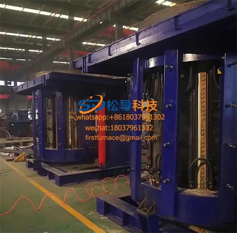
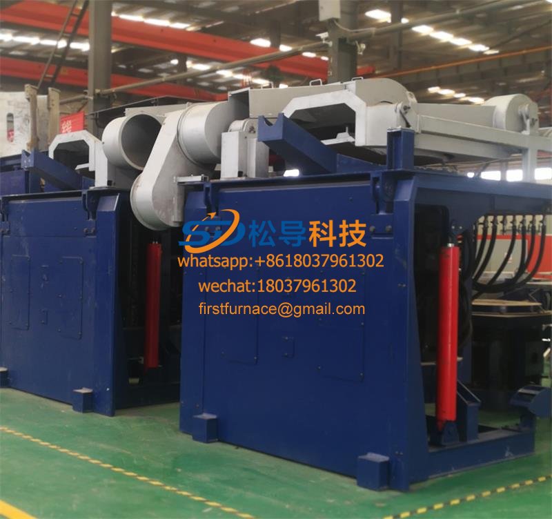
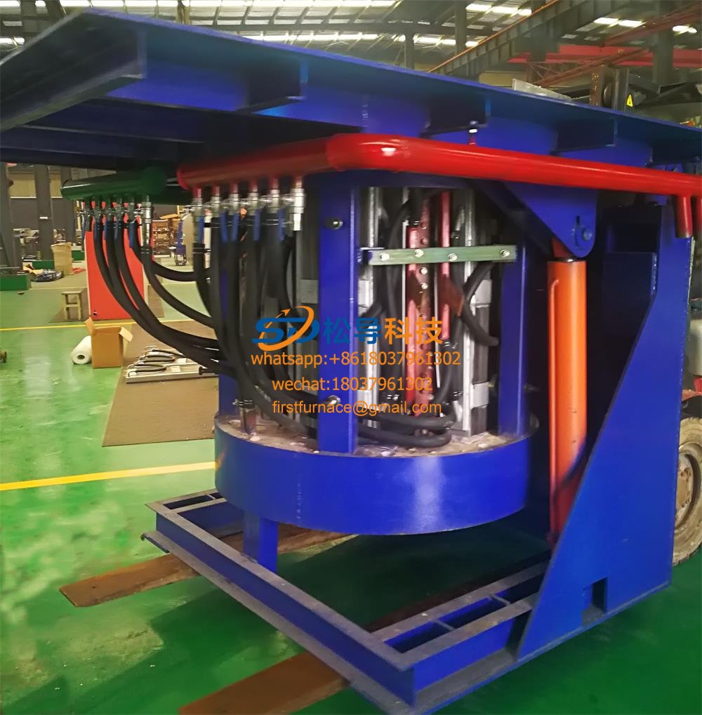
Iron induction furnace
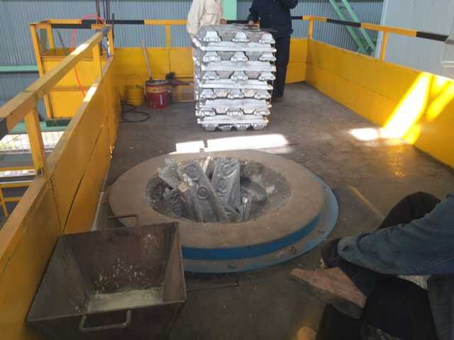
Aluminum melting furnace
Copper melting furnace
Small steel melting furnace
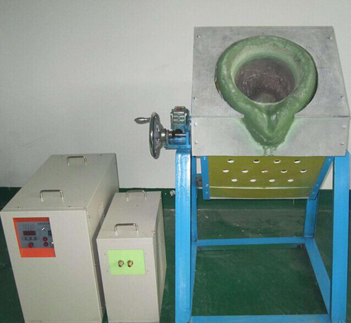
Small induction melting furnace
Induction iron furnace
3T intermediate frequency iron melting f

0.25T Intermediate Frequency Furnace

0.5T Intermediate Frequency Furnace

Medium Frequency Furnace

2T Induction Melting Furnace

1T Induction Melting Furnace

500kg Induction Melting Furnace

250kg Induction Melting Furnace

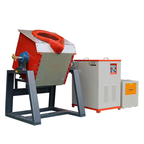
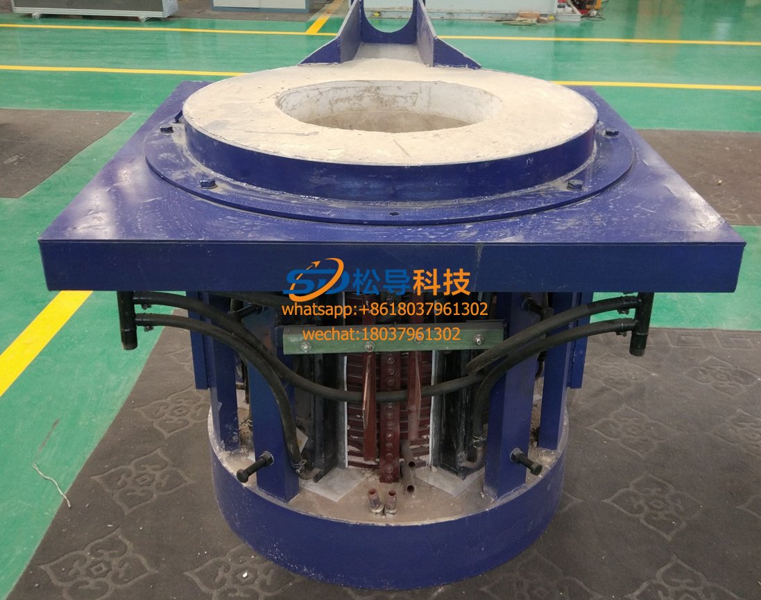
Induction Melting Furnace

3 T Induction Melting Furnace

5T Induction Melting Furnace
1T One Belt Two Intermediate Frequency F

5T One Belt Two Intermediate Frequency F
3T One Belt Two Intermediate Frequency F
2T One Belt Two Intermediate Frequency F
5T Parallel Intermediate Frequency Furna

5T Intermediate Frequency Furnace

5T Series Intermediate Frequency Furnace
3T Series Intermediate Frequency Furnace
2T Series Intermediate Frequency Furnace
1T Series Intermediate Frequency Furnace
0.5T Series Intermediate Frequency Furna

0.25T Series Intermediate Frequency Furn
1T Parallel Intermediate Frequency Furna
2T Parallel Intermediate Frequency Furna
0.5T Parallel Intermediate Frequency Fur
Product Class