Contact
Tel: 18037961302
Sales hot line ( 24 hours service): 18037961302
Sales hot line ( 24 hours service): 18037961302
E-Mail: firstfurnace@gmail.com
whatsapp:+8618037961302
Adress: Luoxin Industrial Park, Luoyang, HenanLarge diameter steel pipe quen
Piston rod quenching and tempe
Grinding rod quenching and tem
High frequency induction heate
Quenching equipment for machin
Round steel end heating furnac
Steel pipe heat treatment prod
Square steel quenching and tem
Sucker rod quenching and tempe
Thickened petroleum steel pipe
Round steel quenching and temp
Steel pipe quenching and tempe
Steel plate quenching and temp
Induction Hardening Machine&nb
Flywheel ring gear high freque
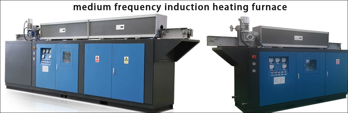
Electric furnace principle(原理)
What should be considered in the energy saving of induction melting furnace?
First, the rectifier transformer
Make sure that the transformer supplier understands the load type of the transformer. It is known that the transformer load of the intermediate frequency power supply is a rectified load and should be maintained at the efficiency of the main nameplate of the transformer. Usually we measure the loss caused by the harmonics of the transformer by the K factor. Usually, the K-factor of the 6-pulse rectifier transformer is K-9, and the K-factor of the 12-pulse rectifier transformer is K-4. The efficiency of the rectifier transformer under normal conditions. It is entirely possible to reach 99%, and we usually take a minimum of 98.5%.
Second, the transformer incoming line
The energy loss of the connecting line of the secondary and intermediate frequency power supply of the transformer is very small. Considering the normal current density to consider the busbar and the cable, the energy loss per meter is 6/V%. Here, V is the incoming line voltage of the intermediate frequency power supply. For example, the primary voltage of the transformer is 10KV, the secondary voltage is 575V, and the transformer is as close as possible to the power supply. In any case, minimizing the distance between the transformer and the power supply is beneficial to reducing the energy loss on the power supply side.
For example: the secondary 575V of the transformer, the distance of 20 meters has a loss of 0.2%.
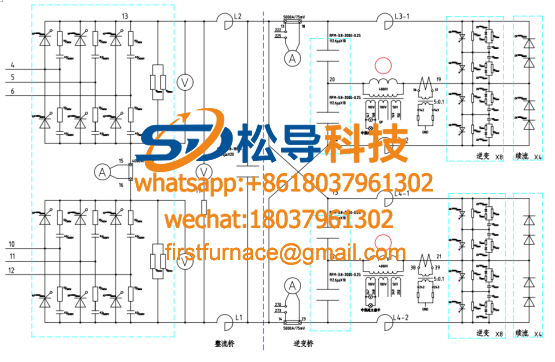
Third, the intermediate frequency power supply
The loss of the IF power supply depends mainly on the type of inverter (voltage type / current type, IGBT / SCR) and frequency.
Through the above comparison, there are some relatively small differences. In the low frequency operation, the loss of the IGBT is higher than that of the SCR, and the number of IGBTs should be larger under the same current condition. However, as the frequency increases, the rated capacity of the SCR decreases, and generally above 2 KHz, the IGBT becomes more advantageous.
Fourth, the resonant capacitor
The loss of the resonant capacitor is usually considered to be ~0.15W/100kVAr. Whether it is series resonance or parallel resonance, it is a power factor for compensating coil hysteresis for the resonant capacitor, so there is not much difference in loss.
However, in practice, large-capacity capacitors have more energy-consuming advantages. Because of the use of large-capacity capacitors, the size of the capacitor cabinet can be reduced, the number of capacitors can be reduced, and of course, the number of capacitor busbars can be reduced. The consumption is relatively low.
Fifth, the output busbar
We consider the normal current density. Typical losses can be estimated using the following data:
For water-cooled busbars, the loss per meter is 0.1%
For air-cooled busbars, the loss per meter is 0.065%.
Therefore, from the perspective of energy loss, it is especially important to minimize the distance between the inverter output and the electric furnace and the length of the water-cooled cable. Although the air-cooled busbars are more efficient, the air-cooled busbars require more busbars and more cooling space to operate. Double the number of busbars does not reduce the general loss. The following is obvious:
The copper busbar has a resistivity of 1.86u-ohm cm at 40 degrees Celsius (assuming the cooling water temperature is below 40 degrees Celsius)
The copper busbar has a resistivity of 2.16u-ohm cm at 85 degrees Celsius (assuming an ambient temperature of 35 degrees Celsius)
When using a water cooled busbar, the corresponding energy loss is 1.86 x 1^2 = 1.86
When using two air-cooled busbars, the corresponding energy loss is 2.16*((1/3)^2 + (2/3)^2) = 1.20 because the flow rate of the two busbars is not 50/50. It is 33/67.
Sixth, water-cooled cable
Normally: the loss of water-cooled cable is: 0.23%/m
The energy loss of water-cooled cables is much higher than that of the output busbars. Therefore, it is especially important to reduce the length of water-cooled cables as much as possible. It is also helpful to increase the number of water-cooled cables to reduce energy consumption, but usually, Excessive water-cooled cables in the furnace are not practical.
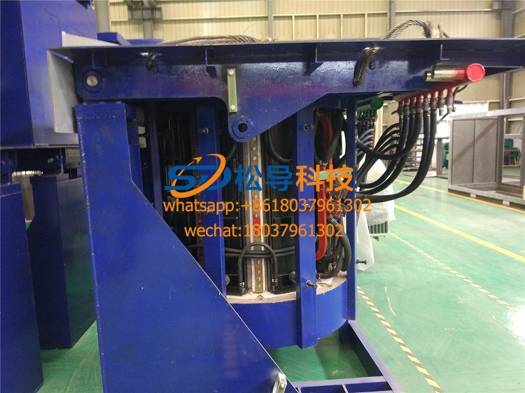
Seven, the electric furnace part
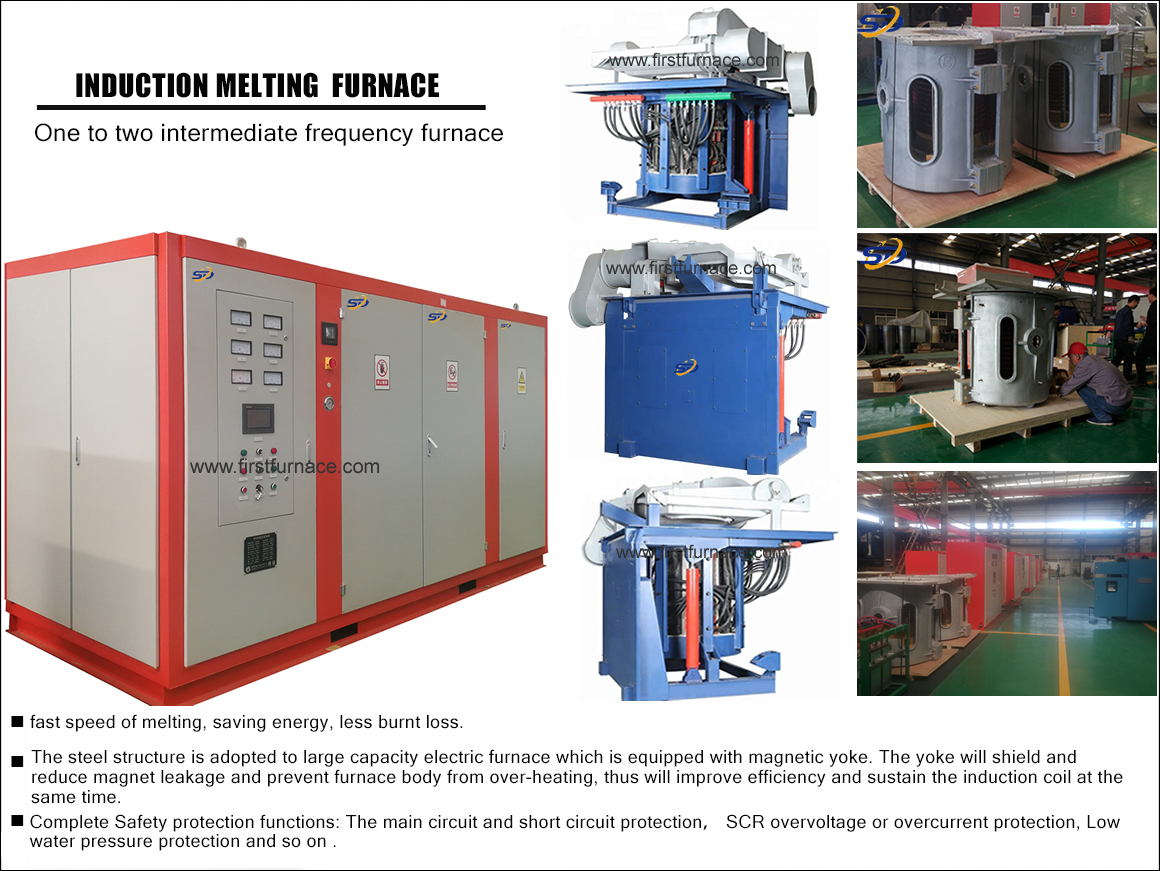
The circuit part is the part with the largest energy loss, but energy can be saved by the following means:
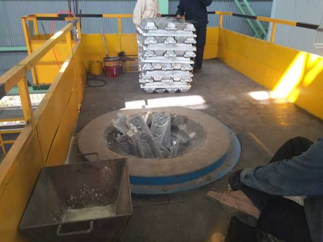
--- Use a good, clean charge
--- Organize the good charge and shape to improve the furnace utilization rate
--- Develop a good habit of covering the lid
--- Maintain the lining, avoid bypassing, do not continue to use the lining is too thin
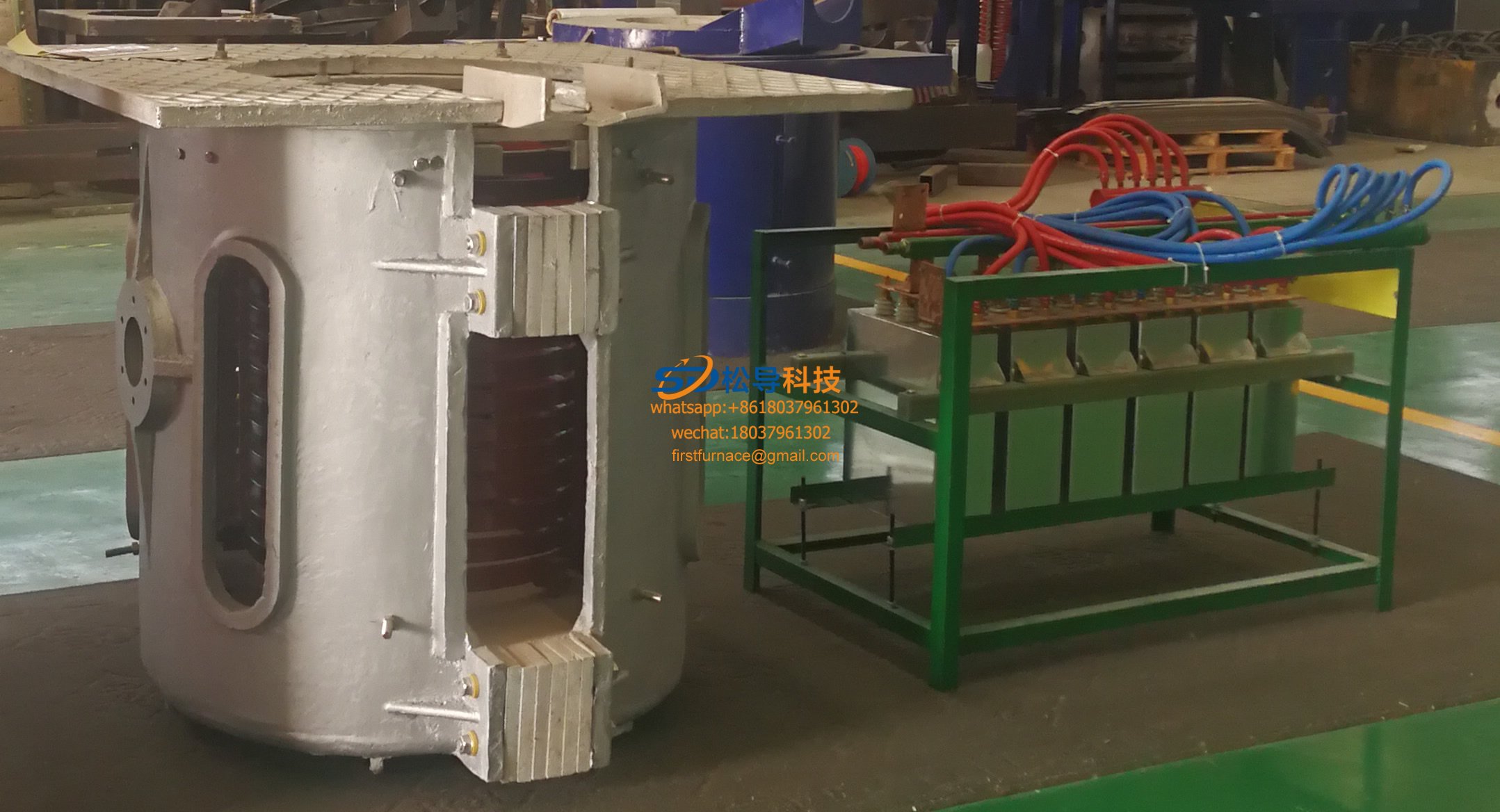
7.1 Electrical losses
The electrical efficiency of the induction coil mainly depends on the shape of the coil, the resistivity and frequency of the metal. The diameter and height ratio of the effective coil is 1, the inner diameter of the molten pool is 0.75-0.8 of the inner diameter of the coil, and the operating frequency is 200 to 300 Hz. Part of the electrical losses are:
Electrical loss of the coil: about 18%
Loss of yoke and shorting ring: about 1.5%
The total loss is: 19.5%
The above calculations are based on the design that the cross-sectional area of the coil copper tube is a rectangular tube, the duty ratio of the coil is greater than 0.8, and the coil of the coil of the rectangular tube is about 3% higher.
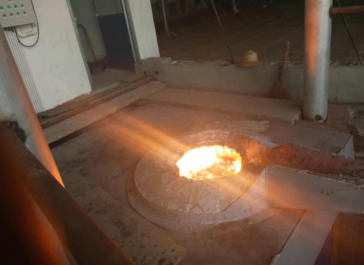
7.2 heat loss
The heat loss is mainly determined by the thermal conductivity of the lining material, but for cast iron applications, it is usually lining with quartz sand.
Furnace with furnace cover and power density of 500KW/ton, heat loss is 10.6% - 2.3% (1 ton - 25 tons)
Furnace with furnace cover and power density of 750KW/ton, heat loss is 7.1% - 1.5%
Without a furnace cover, the power density is 500KW per ton of melting furnace, the heat loss is 24.2% - 6.9% (1 ton - 25 tons)
Without the furnace cover, the power density is 750KW per ton of melting furnace, the heat loss is 16.1% - 4.6%
From the above comparison, we can clearly see that the design of the high power density belt cover can improve the efficiency, and has obvious advantages in the full-temperature hot metal insulation or heating.
7.3 Comprehensive consideration of electrical loss and heat loss
From the comparison of the following tables, we can see that the effect of heat loss and electrical loss on the overall loss of the intermediate frequency melting furnace is very interesting.
The curves below show that the lining of the lining reduces the efficiency of the furnace while increasing the thickness of the lining to increase the life of the lining. When the thickness of the lining is reduced to increase the efficiency of the electric furnace, the consequence is that the life of the lining is shortened. Past experience tells us that when the thickness of the lining is burned to 2/3 of the design thickness, a new lining should be replaced. The ratio of the inner diameter of the furnace to the inner diameter of the coil is 0.75-0.83, and the large furnace is 0.8-0.87. The range of efficiencies for electric furnace operation.
Loss of other auxiliary systems
There are several sets of auxiliary systems installed in the medium frequency induction furnace. They include the following systems.
---cooling system
---Hydraulic system
---Dust removal system
When the electric furnace is running, the water cooling system will continue to work continuously. After the electric furnace stops running, the cooling system will continue to run for several hours until the electric furnace is completely cooled.
Usually the form of the cooling system is different (open circuit cooling system, closed circuit cooling system, evaporative cooling tower, dry cooling tower, water saving type) but the closed cooling tower system is very common in use. There are usually pumps, cooling tower spray pumps, cooling tower fans, because the circulating water flow is proportional to the power of the intermediate frequency electric furnace, the pump power is also proportional to the flow, so we can think of the pump power and medium frequency electric furnace Power is also a proportional relationship.
The cooling capacity of the cooling system is also proportional to the power of the electric furnace, so the power required to operate the cooling tower is also proportional to the power of the electric furnace; the following is a relationship between the operating power of the cooling tower and the electric power of the electric furnace:
Therefore, in an electric furnace system, the energy consumption of the cooling system equipment accounts for 1.2% of the entire intermediate frequency electric furnace melting system.
Here are some ways to reduce energy consumption:
l Ensure that the temperature switch controlled by the cooling tower fan is working properly and the set temperature value is not too low;
l Ensure the water quality of the external circulation water is clean
l Ensure that the cooling tower spray pipe is unobstructed, the cooling tower coil is clean, and maintain high cooling efficiency.
l Ensure that the spray pump of the cooling tower is turned on and off before the fan of the cooling tower to avoid fouling of the coil of the cooling tower.
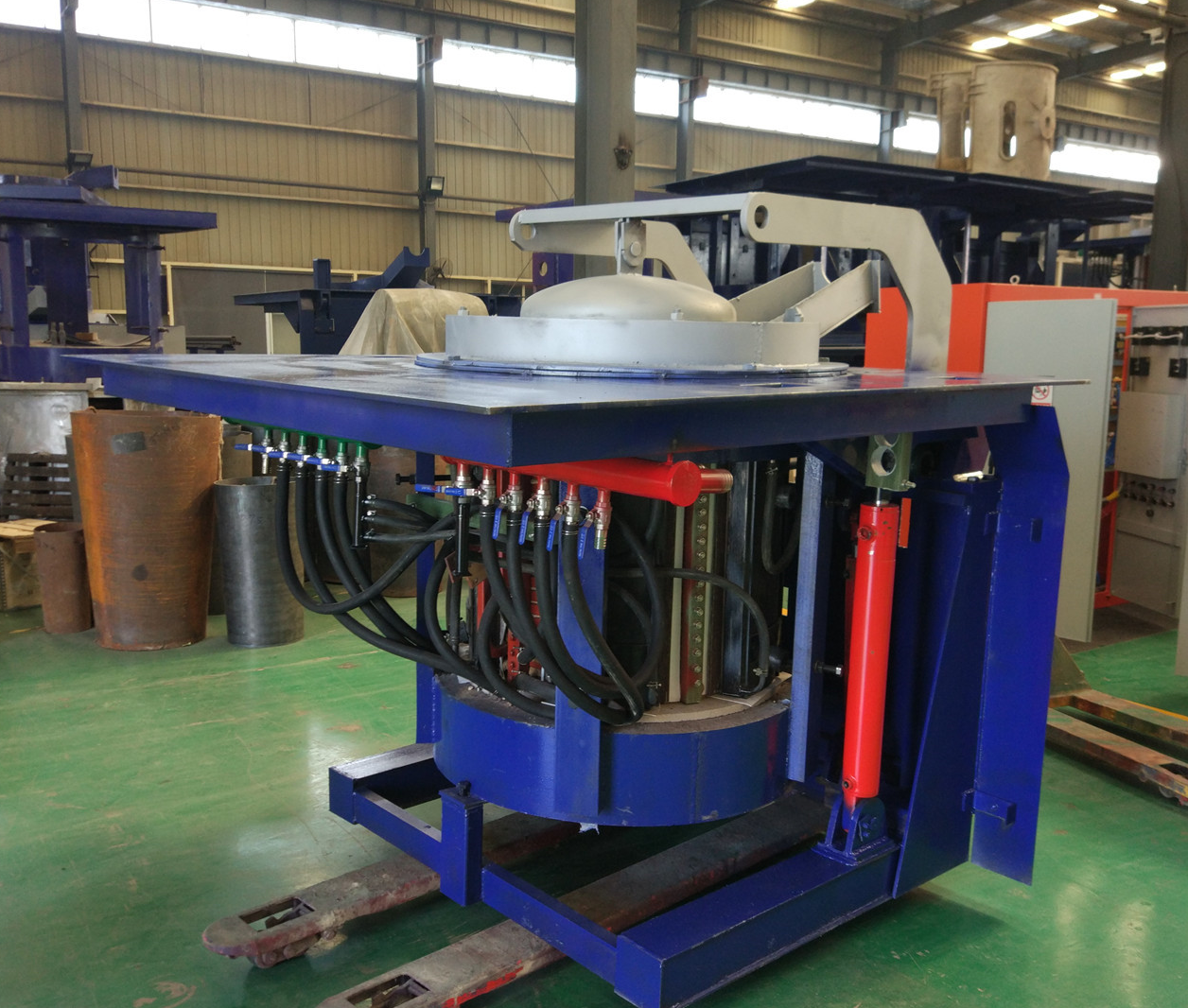
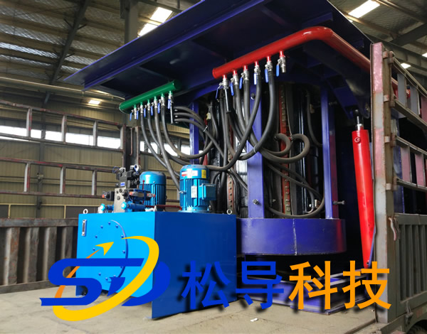
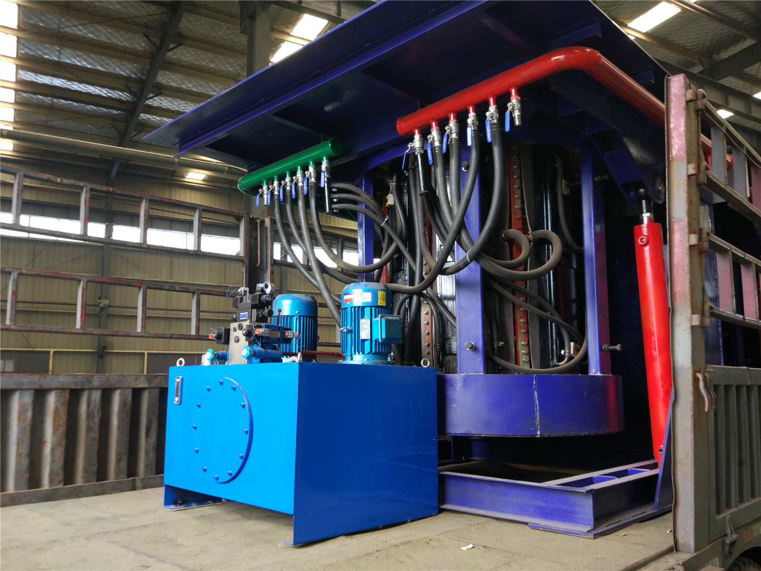
Hydraulic system
The size of the hydraulic pump in the hydraulic system has a direct relationship with the size of the intermediate frequency electric furnace, ensuring a two-minute tilting time. The size of the hydraulic pump is about three times the tonnage of the electric furnace. For example, a 10-ton electric furnace, hydraulic system hydraulic system The pump has a power of 30 kW.
So if the operating time of the hydraulic pump is 10 minutes in an hour, the power density of the electric furnace is 500KW/ton, the energy consumption of the hydraulic system accounts for 0.1% of the whole system, and the power consumption of the system is very small, but the hydraulic system is not needed. The hydraulic system should be closed in time.
Vacuum cleaner for electric furnace
Due to the demand for air volume of the dust suction device, the power of the fan of the dust suction device depends on the size of the electric furnace tonnage and the type of the furnace cover, and what kind of charge is melted (for example, the fan power of the vacuum hood is higher than that of the suction device). The dust ring needs to be doubled.) Generally speaking, the power of the fan is proportional to the cube root of the tonnage of the furnace.
Based on the calculation of the suction ring, the energy consumption of the vacuum system is such a range: the energy consumption of the 1 ton furnace vacuum system is 0.4% of the system. The 25-ton furnace vacuum system accounts for 0.14% of the entire melting system. For the melting system of the one-to-one electric furnace, we don't have much energy-saving work to do, but for the multi-electric furnace melting system, the furnace should have a corresponding switching device when it does not require a vacuuming device.
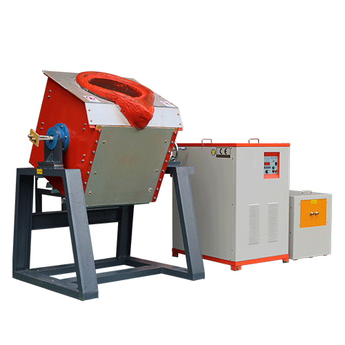
Iron induction furnace
Aluminum melting furnace
Copper melting furnace
Small steel melting furnace
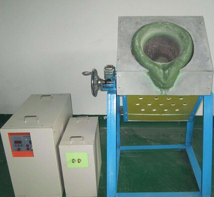
Small induction melting furnace
Induction iron furnace
3T intermediate frequency iron melting f

0.25T Intermediate Frequency Furnace

0.5T Intermediate Frequency Furnace

Medium Frequency Furnace

2T Induction Melting Furnace

1T Induction Melting Furnace

500kg Induction Melting Furnace

250kg Induction Melting Furnace

Induction Melting Furnace

3 T Induction Melting Furnace

5T Induction Melting Furnace
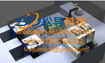
1T One Belt Two Intermediate Frequency F

5T One Belt Two Intermediate Frequency F
3T One Belt Two Intermediate Frequency F
2T One Belt Two Intermediate Frequency F
5T Parallel Intermediate Frequency Furna

5T Intermediate Frequency Furnace

5T Series Intermediate Frequency Furnace
3T Series Intermediate Frequency Furnace
2T Series Intermediate Frequency Furnace
1T Series Intermediate Frequency Furnace
0.5T Series Intermediate Frequency Furna

0.25T Series Intermediate Frequency Furn
1T Parallel Intermediate Frequency Furna
2T Parallel Intermediate Frequency Furna
0.5T Parallel Intermediate Frequency Fur
Product Class